
Planetary Gear Motor Stages: 1-Stage vs 2-Stage vs 3-Stage
A planetary gear motor looks simple from the outside: a can, a shaft, a ratio. Open the gearbox, though, and the real decision sits one level deeper — how many planetary stages the ratio is split across. Stage count decides how long the gearbox is, how much of the motor’s torque actually survives to the output shaft, how much backlash your positioning loop has to absorb, and how much the assembly costs. Two gearboxes with the same 64:1 ratio can behave very differently once you know that one of them gets there in two stages and the other in three.
This guide explains what a stage physically is, shows the stage table we publish for our own 22 mm planetary platform — including the efficiency and length penalties most suppliers leave out of the brochure — and walks through a worked example where the ratio math says one thing and the gearbox torque rating says another. If you want the wider context first, our DC planetary gear motor product line lists the ratios and torque ranges this article refers to.
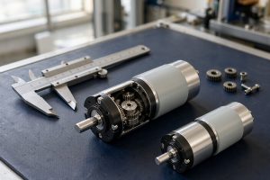
A 22 mm-class planetary gear motor opened on the bench: sun gear, planet gears and ring gear visible in the first stage.
What a Stage Actually Is Inside a Planetary Gearbox
One stage is one planetary gear set: a sun gear in the middle, three or four planet gears around it, and a fixed ring gear (internal gear) wrapping the outside. The motor drives the sun; the planets walk around inside the ring; the carrier that holds the planet pins becomes the output of that stage. If you need a refresher on the components themselves, our overview of what a planetary gear motor is covers the geometry in detail.
For the common arrangement — sun input, ring fixed, carrier output — the single-stage reduction ratio is:
i = 1 + Zr / Zs
where Zr is the ring gear tooth count and Zs is the sun gear tooth count. A ring with 60 teeth and a sun with 20 teeth gives 1 + 3 = a 4:1 stage. That formula also explains why single stages top out low: to reach 10:1 with a 20-tooth sun you would need a 180-tooth ring, and the ring gear diameter grows with tooth count. In a 22 mm gearbox there simply is not room, which is why small planetary platforms multi-stage instead of over-sizing one stage.
How Stages Stack: Ratio Multiplies, Efficiency Multiplies Too
When one stage’s carrier drives the next stage’s sun, ratios multiply and so do losses. A 4:1 stage followed by a 4:1 stage is 16:1, not 8:1. If each stage transfers power at roughly 90%, two stages deliver about 81% of input power, three about 73%, and so on. This compounding is the single most misunderstood thing about multi-stage planetary gearboxes: the ratio is free, the efficiency is not.
The Stage Table We Publish for a 22 mm Planetary Platform
Below is the actual stage table from the product page of our DM-22PM2140 planetary gear motor, a 22 mm brushed planetary platform rated 6–24 V with output speeds from 3 to 1,500 rpm. We publish it because the numbers answer most stage-count questions at a glance:
| Stages | Reduction ratios available | Gearbox length | Breaking torque | Gearbox efficiency |
|---|---|---|---|---|
| 1 | 4, 4.75 | 15.2 mm | 2 N·m | 90% |
| 2 | 16, 22.5 | 19.8 mm | 3 N·m | 81% |
| 3 | 64, 79, 107 | 24.4 mm | 4 N·m | 73% |
| 4 | 256, 361, 509 | 29 mm | 5 N·m | 65% |
| 5 | 1024, 2418 | 33.6 mm | 5 N·m | 59% |
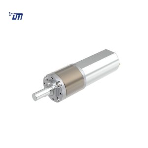
DM-22PM2140, the 22 mm planetary platform the stage table above is taken from.
Three things in this table deserve a closer look. First, the efficiency column is almost exactly 0.9 raised to the power of the stage count — 90%, 81%, 73%, 65%, 59% — which confirms the per-stage loss model rather than a marketing rounded number. Second, gearbox length grows by roughly 4.6 mm per stage; a five-stage build is more than twice as long as a single stage in the same diameter. Third, breaking torque plateaus at 5 N·m from stage four onward, because the final stage’s gears and carrier bearings — not the ratio — set the mechanical ceiling.
1-Stage vs 2-Stage vs 3-Stage: What Actually Changes
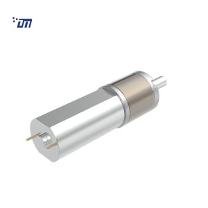
Rear three-quarter view of the same DM-22PM2140: motor can and supply terminals sit behind the gearbox section.
The table below condenses the trade-offs engineers weigh when fixing stage count. It is a decision map, not a law of physics — specific designs vary.
| Factor | 1 stage | 2 stages | 3 stages |
|---|---|---|---|
| Typical total ratio | 3:1 – 10:1 | 10:1 – 30:1 | 30:1 – 150:1 |
| Gearbox efficiency (small DC class) | ~90% | ~81% | ~73% |
| Length penalty | Baseline | +1 gear set | +2 gear sets |
| Backlash accumulation | Lowest | Adds 1 mesh | Adds 2 meshes |
| Max continuous torque | Limited by ratio | Higher | Highest, then plateaus |
| Relative cost | Lowest | Medium | Higher |
| Typical fit | Speed reduction with modest torque | General automation | Low speed, high torque |
Where the Efficiency Actually Goes
Each stage loses power in tooth meshing (rolling plus a sliding component away from the pitch point), in the planet pins and bearings, in churning grease, and in seal drag. Reference works such as RoyMech’s gear efficiency guide break these losses down by mesh type, and the same energy-accounting logic that IEC 60034-2-1 applies to electrical machine losses applies here: name the loss paths, then measure them separately. A single well-made miniature stage transfers around nine tenths of input power; the remaining tenth turns into heat inside the gearbox. That heat is not free to ignore: a three-stage box doing the same output work as a one-stage box dumps roughly three times the gearbox heat into your housing. In sealed or high-ambient products this is why we ask about duty cycle before quoting a stage count — sustained low-speed high-torque duty in a hot enclosure is where over-staged gearboxes cook their grease. For the motor-side loss half of the story, see our article on DC motor overheating causes and prevention.
The Length and Mass Penalty Is Real
At 22 mm frame size the gearbox grows 4.6 mm per stage. That sounds trivial until the stage count pushes the assembly past the length your enclosure reserved for it — one of the most common late-stage redesign requests we see. Decide the stage count before the mechanical enclosure is frozen, not after.
Choosing Stage Count From a Required Ratio
The practical selection logic we use when quoting:
- Up to about 5:1 — one stage. Highest efficiency, shortest body, fewest meshes to generate noise and backlash.
- 5:1 to about 25:1 — two stages. The workhorse range for automation at this frame size; 16:1 and 22.5:1 cover most conveyors, actuators and pump drives.
- 25:1 to about 100:1 — two or three stages depending on the torque and length budget. Three stages buy ratio at the cost of nine points of efficiency per added stage.
- Above 100:1 — three stages up to ~150:1; beyond that, four or five stages, accepting 59–65% efficiency, or move to a larger frame / different gear family. Our comparison of planetary vs worm gear motors covers when a worm box is the better high-ratio choice despite its own efficiency tax.
One honest caveat: these bands describe our own 22 mm platform’s ratio ladders. Other suppliers’ single stages may reach 6:1 or higher, which shifts every band. Always read the stage table of the actual gearbox, not the generic band.
Worked Example: When the Ratio Math and the Torque Rating Disagree
Consider a hypothetical 24 V actuator that needs about 45 rpm at the output shaft. Our brushed motor stage runs 3,000 rpm at the rated point we are designing to, so the required ratio is 3,000 ÷ 45 ≈ 67:1. The two-stage ladder tops out at 22.5:1 — not enough. The three-stage ladder offers 64:1 and 79:1. So far, three stages looks mandatory.
Now check torque. Assume the motor’s rated torque at this operating point is 1.2 kgf·cm. Through a 64:1 three-stage gearbox at 73% efficiency, theoretical output torque is:
1.2 kgf·cm × 64 × 0.73 ≈ 56 kgf·cm ≈ 5.5 N·m
But the stage table caps the three-stage box at 4 N·m breaking torque. The ratio math promises torque the gearbox cannot mechanically deliver — the last stage becomes the fuse. Two valid fixes, and this is the decision I would actually make: if the duty allows, drop to the two-stage 22.5:1 build, which gives 133 rpm output and 1.2 × 22.5 × 0.81 ≈ 22 kgf·cm (2.1 N·m) at 81% efficiency — shorter, cooler, and inside every rating. If 45 rpm is a hard requirement, keep three stages but specify a motor with lower rated torque (or a current-limited driver) so the gearbox rating is respected, and treat 4 N·m as the design ceiling. Either answer is defensible; ignoring the plateau is not.
For the full torque-and-speed calculation behind this example — including the motor’s torque–speed line and stall current — see our step-by-step guide to planetary gear motor torque and speed ratio calculation.
When Adding Stages Is the Wrong Answer
The most common mistake we see in RFQs is treating stage count as a free way to buy ratio. It is not, for three reasons.
Backlash accumulates. Each stage adds its own mesh clearance, and the total angular play at the output is roughly the sum of what each mesh contributes. You can see this on any bench with a dial indicator: clamp the indicator against a pin on the output shaft, rock the shaft within its free play, and read the total travel before the gears take up load — then repeat the same measurement on a lower-stage-count box and compare. A positioning loop that barely tolerates a two-stage box may hunt visibly on a four-stage one. If repeatability matters, say so in the RFQ and let the gearbox be built to it.
Noise and wear start at the fastest stage. The first stage runs at motor speed and sees the most mesh cycles per second; the last stage carries the most torque. A five-stage gearbox running 1,000:1 from a 6,000 rpm motor puts 6,000 rpm through its first two meshes — grease specification and gear quality at that end decide the acoustic profile. How gear motor noise is measured and reduced deserves its own checklist, and stage count is one of its inputs.
Planetary stages never self-lock. Unlike a worm set, a planetary train back-drives. If your load can back-drive the output — a vertical axis, a lifting column — stage count will not save you; you need a brake or a worm stage. This is a frequent late discovery in sampling and holding applications.
There is also a cost crossover worth naming: past roughly 3–4 stages, a larger-diameter gearbox with fewer stages often wins on both price and efficiency, because torque capacity scales with gear size faster than ratio scales with stages. For high-torque mobile platforms such as AGV and AMR drive systems, that is usually the better trade.
What to Put in the RFQ So Stage Count Is Decided Correctly
When you send a stage-count-sensitive requirement to any supplier — us included — put these in writing:
- Required output speed and torque at the duty point, not peak values; continuous vs intermittent duty separately
- Allowable gearbox length and diameter, so the stage ladder is chosen inside your envelope
- Allowable backlash at the output shaft, if positioning matters
- Voltage and control type (PWM, driver current limit), because the motor’s operating point shifts what ratio the gearbox needs
- Ambient temperature and enclosure, since multi-stage efficiency losses end up as heat in your housing
- Expected service life and lubrication constraints for low-speed high-torque duty
A supplier who answers with a stage table, an efficiency figure and a breaking torque figure — not just a ratio — is a supplier who has actually built the gearbox. Our engineering contact page exists for exactly this kind of exchange.
FAQ
Does a higher stage count always mean more output torque?
No. More stages multiply the ratio, and ratio multiplies theoretical torque — but each stage’s efficiency multiplies the losses, and the gearbox’s breaking torque caps what the output can mechanically take. On our 22 mm platform, torque capability plateaus at 5 N·m from four stages onward regardless of ratio.
What ratio requires a three-stage planetary gearbox?
In the 22 mm class, two-stage ladders end around 22:1–30:1, so requirements above roughly 30:1 move to three stages (64:1 to 107:1 on our ladder). The exact boundary depends on the supplier’s tooth counts, so compare stage tables rather than generic bands.
Does stage count affect backlash and noise?
Yes to both. Each added stage contributes its own mesh clearance to total output backlash, and the fastest (first) stage generates the most mesh-cycle noise. Fewer stages is the cheaper route to a quiet, repeatable drive.
Can I get more than 1000:1 from a small planetary gearbox?
On our 22 mm platform the five-stage ladder reaches 1024:1 and 2418:1, at 59% gearbox efficiency and a 33.6 mm length. That is a valid solution for very slow, light-load outputs — but check whether a larger two- or three-stage box would deliver the same output work with less heat and fewer losses.
Why not just make the ring gear bigger for a high single-stage ratio?
Single-stage ratio is 1 + Zr/Zs, so high ratios need physically large ring gears. In compact diameter classes there is no room; multi-staging is how small planetary gearboxes reach high ratios without growing in diameter.
Related Reading
- Planetary Gear Motor vs Spur Gear Motor: A Complete Comparison
- How to Read a Motor Datasheet: Stall Torque, No-Load Speed and the Rated Point
- How Noise and Vibration in DC Gear Motors Are Measured and Reduced
- BLDC Planetary Gear Motor Types, Features and Functions