
How to Calculate Planetary Gear Motor Torque and Speed Ratio
A planetary gear motor looks easy to size on paper: divide speed by the ratio, multiply torque by the ratio, done. That shortcut is exactly why so many prototypes show up underpowered or 20% slower than the spec promised. The gap between the napkin calculation and the motor that actually drives your machine comes down to three things most people skip: where the motor really sits on its torque–speed line, how the ratio splits into gear stages, and how efficiency compounds stage by stage.
This guide walks through a complete planetary gear motor torque calculation for the small DC gear motors used in AGVs, medical devices, valves and smart equipment — the 12–24 V, φ20–φ50 mm class. Every step uses numbers you can check, and the worked example at the end sizes a real 24 V drive wheel. If you are still comparing gear families, start with our DC planetary gear motor product line to see the ratio and torque ranges this article assumes.
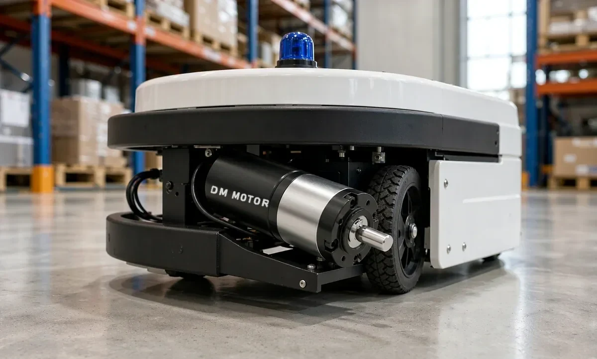
A 24 V planetary gear motor driving an AGV wheel: the load sets the operating point, not the datasheet.
Start From the Motor Line, Not From the Gearbox
A small permanent-magnet DC motor has a roughly linear torque–speed curve. Two numbers define it: no-load speed (n₀) at zero torque, and stall torque (Tₛ) at zero speed. Everything in between sits on the line connecting them.
Take a typical 24 V motor with 6,500 rpm no-load and 0.42 N·m stall torque (4.3 kgf·cm). If your load demands half the stall torque, expect the speed to settle near half the no-load value — about 3,250 rpm — not 6,500 rpm. That single fact kills more first-pass calculations than any other. Datasheets list no-load speed because it is easy to measure, but your loaded motor will never see it.
Brushless motors driven by a closed-loop controller behave differently: the controller holds speed up to the current limit, then torque collapses. Know which animal you have before you calculate. Our guide to reading a motor datasheet covers the stall-torque / rated-point distinction in detail, including why the rated point — not the stall point — is where continuous ratings come from.
One field note from our bench: datasheet curves assume nominal voltage. A “24 V” AGV running on a sagging battery at 21 V loses about 12% of no-load speed and more than that in available torque, and the error compounds through every ratio you apply afterwards. If the numbers matter, measure the loaded speed with a cheap optical tachometer on the output shaft at real load, and treat the datasheet line as the starting estimate rather than the verdict.
Step 1: Turn the Load Into an Output Torque Requirement
The gearbox output must supply the load torque. Calculate it from the physics of your mechanism, not by analogy to a similar machine.
Wheels, rollers and friction loads
For a wheeled platform on a grade:
F = m·g·sin θ + μ·m·g·cos θ
T_wheel = F·r (per driven wheel, after dividing F across the driven wheels)
With m = 45 kg (vehicle + battery + payload), a 5° ramp, a rolling-resistance coefficient μ = 0.02, and Ø100 mm wheels (r = 0.05 m):
- Grade force: 45 × 9.81 × sin 5° = 38.5 N
- Rolling resistance: 0.02 × 45 × 9.81 × cos 5° = 8.8 N
- Total: 47.3 N, split over two driven wheels = 23.7 N each
- Add a 10% margin for weight transfer and uneven floors: 26 N per wheel
- Wheel torque: 26 N × 0.05 m = 1.3 N·m (13.3 kgf·cm)
Lifting and gravity loads
For hoists and lift columns the load never takes a break — gravity applies even at standstill, so the gearbox must hold or the application needs a brake or self-locking stage. A 3 kg payload on a 25 mm drum radius needs 3 × 9.81 × 0.025 = 0.74 N·m (7.5 kgf·cm) continuously. Size the gearbox continuous rating for this number, not the motor’s.
Inertia and acceleration
Accelerating a rotating or translating mass needs extra torque: T_acc = J·α for rotating loads, or F = m·a translated through the wheel radius for linear motion. Two details matter for gear motors:
- The load inertia reflected back to the motor shrinks by i². A 1:30 ratio makes a 0.02 kg·m² load look like 0.000022 kg·m² at the motor shaft — usually negligible, which is a genuine advantage of gear reduction.
- Acceleration torque acts through the same gearbox, so it counts against the gearbox peak rating, not just the motor’s.
Step 2: Choose the Ratio, Then Split It Into Stages
The ratio follows from speed: i = n_motor / n_output. Use the loaded motor speed, not no-load. A PM DC motor at a moderate working point typically delivers 85–90% of no-load speed, so a 6,500 rpm motor under load is closer to 5,800 rpm.
For the AGV wheel needing 191 rpm (1.0 m/s on Ø100 mm wheels):
i = 5,800 / 191 ≈ 30 → 1:30
A single planetary stage realistically delivers 3:1 to 10:1. Beyond that, planet carriers, sun pins and ring gears get stressed, noise climbs, and the tooling cost of unusual tooth counts goes up. So ratios like 1:30 are built by stacking stages, and how you stack them changes the gearbox’s behavior. If you need a refresher on why, our planetary gear motor guide explains the sun–planet–ring arrangement stage by stage.
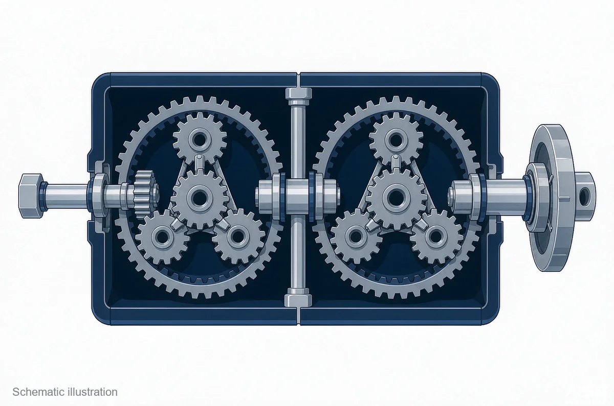
A 30:1 ratio built from a 5:1 and a 6:1 stage — each stage multiplies the ratio and divides the speed. Schematic illustration.
| 1:30 split | Stages | Typical total efficiency | Trade-off |
|---|---|---|---|
| 5:1 × 6:1 | 2 | ~81% | The usual pick; balanced loads and noise |
| 3:1 × 10:1 | 2 | ~81% | The 10:1 second stage runs hot and loud at high input speed |
| 2:1 × 3:1 × 5:1 | 3 | ~73% | Only if a 2-stage layout cannot fit the housing |
For most 24 V drive applications we would rather build 5:1 × 6:1 than chase a single high-ratio stage. Each extra stage multiplies output torque by roughly 0.9; a badly loaded 10:1 stage costs noise and gear life.
Step 3: Multiply Efficiency Stage by Stage
Output torque follows:
T_out = T_motor × i × η_total, where η_total = η_stageⁿ
Datasheet motor torque is measured at the shaft; the gearbox takes its cut before the load sees anything. Planetary stages in this size class run at about 90% each — our gearbox datasheets list 90% for a single stage, compounding to 81% at two stages, 73% at three and 65% at four.
| Gearbox stages | Typical per-stage η (metal gears, grease) | Total η | Torque delivered from 0.42 N·m motor at 1:30 |
|---|---|---|---|
| 1 | 90% | 90% | 11.3 N·m |
| 2 | 90% | 81% | 10.2 N·m |
| 3 | 90% | 73% | 9.2 N·m |
Three practical notes:
- Efficiency depends on input speed, temperature and lubrication, not just stage count. Numbers above are nominal room-temperature values.
- When a datasheet quotes gearbox efficiency, check whether it states test conditions. Efficiency measurement of rotating machines is standardized in IEC 60034-2-1; reputable manufacturers test at defined speed and temperature points, and “efficiency” measured at a different point can differ by several points.
- Worm gearboxes trade torque for self-locking at 50–70% efficiency. When the load needs every watt-hour — battery-powered AGVs above all — that difference compounds every cycle. Our planetary vs worm gear motor comparison walks through when the self-locking trade is worth it.
Worked Example: Sizing a 24 V Planetary Gear Motor for an AGV Drive Wheel
Here is the full calculation for the vehicle from Step 1, with both driven wheels on a 1:30 two-stage planetary gearbox.
Requirements: 45 kg vehicle, 1.0 m/s target speed, 5° ramp, Ø100 mm wheels, accelerate to full speed in 0.8 s.
- Output speed. 1.0 m/s ÷ 0.3142 m wheel circumference × 60 = 191 rpm. With the motor loaded at 5,800 rpm, i = 1:30 gives 193 rpm output — 1.0 m/s, on target.
- Continuous torque on the ramp. 1.3 N·m per wheel (13.3 kgf·cm, from Step 1). Check against the gearbox continuous rating: a φ32 mm-class micro planetary box is commonly rated in the 2–3 N·m range continuous, so 1.3 N·m sits at 45–65% utilization — a sane margin. Always verify against the specific datasheet, because ratings vary widely at this size.
- Acceleration check. 0→1.0 m/s in 0.8 s means a = 1.25 m/s², adding 56.3 N across the vehicle. Worst case (launch on the ramp): 47.3 + 56.3 = 103.6 N total → 51.8 N per wheel → with the 10% margin, 2.9 N·m (29.5 kgf·cm) peak per wheel. This exceeds the continuous rating, which is fine if the gearbox has a peak/intermittent rating — many micro planetary boxes allow 2–3× continuous for short events. Verify it in the datasheet; if the box has no peak rating, treat its continuous rating as the ceiling.
- Motor-side torque. Peak motor torque = 2.9 / (30 × 0.81) = 0.12 N·m — 29% of the 0.42 N·m stall torque. Comfortable.
- Current draw on the ramp. Per wheel, P_out = 1.3 N·m × 20.2 rad/s = 26.3 W. With an 81% gearbox and ~60% motor efficiency at this point, P_in ≈ 54 W → 2.3 A per motor at 24 V, ~4.5 A for the pair. Size the fuse and battery BMS for the acceleration case, not the cruise case — startup current is how controllers die young.
The deeper pattern in this AGV example — matching load, ratio and duty against both motor and gearbox ratings — is the same one behind high-torque planetary gear motors for AGV and AMR drives, where the gearbox rating usually binds before the motor does.
A practical close-out step: after assembly, clamp a DC current meter on one motor lead and drive the vehicle up the ramp. If the measured current exceeds your calculation by more than about 25%, the usual culprits are wheel drag (a caster riding sideways), a gearbox running dry of grease, or a real-world ramp steeper than the drawing said. Current is the cheapest truth-teller in the whole chain — the motor consumes watts in proportion to torque, so the meter reads the sum of every friction loss you forgot.
Peak Torque, Duty Cycle and Heat
Continuous ratings exist because heat, not magnetism, is what kills small motors. Three checks separate designs that survive from designs that cook:
Separate continuous from peak. Stall torque is a starting number, not an operating point. Run a motor anywhere near stall and it converts your battery into heat at an impressive rate. We size for continuous torque at 70–80% of the rated value and save headroom for acceleration and jams.
Classify the duty cycle. IEC 60034-1 defines the standard duty types — S1 continuous, S2 short-time, S3 intermittent periodic — and they matter even for micro motors: a valve actuator that runs 10 seconds every 5 minutes can safely peak far above what an 8-hour conveyor motor may sustain. The IEC 60034-1 rating and performance standard is the reference behind those classifications.
Watch the gearbox temperature too. Grease viscosity drops as the gearbox warms, efficiency falls, and the losses feed back into more heat. In sealed housings with no airflow, derate another 10–15%. If your application runs hot anyway, our DC motor overheating guide lists the failure chain and how to break it.
Six Mistakes That Sink Planetary Gear Motor Torque Calculations
- Using stall torque as the continuous rating. Stall is a 1-second number. Continuous torque is typically 15–25% of stall for small PM DC motors.
- Calculating output speed from no-load speed. Under real load the motor settles 10–15% below no-load. Multiply that error by your ratio and the AGV misses its speed target before the first test run.
- Quoting efficiency once instead of per stage. A “90% efficient” 3-stage box is usually 90% per stage → 73% total. At 1:100 ratios this is the difference between 9.0 N·m and 7.3 N·m at the output.
- Mixing torque units. 1 kgf·cm = 0.0981 N·m. A 12 kgf·cm gearbox requirement entered as 12 N·m oversizes the design by an order of magnitude. Pick one unit, convert once, and label every number.
- Ignoring the gearbox continuous rating. At high ratios the gearbox output limit — not the motor — decides what the assembly can deliver. This is the most common sizing failure we see in high-ratio requests.
- Forgetting the acceleration case. The steady-state calculation passes; the motor stalls on the first start against a loaded conveyor. Always check T = J·α (or m·a) plus static load together.
Quick Reference: Formulas and Conversions
| Quantity | Formula | Notes |
|---|---|---|
| Gear ratio | i = n_motor / n_output | Use loaded motor speed |
| Output speed | n_out = n_motor / i | No-load basis; expect 10–15% drop loaded |
| Output torque | T_out = T_motor × i × η_total | η_total = η_stageⁿ |
| Wheel/roller torque | T = F × r | F from grade + rolling resistance |
| Grade + rolling force | F = m·g·sin θ + μ·m·g·cos θ | μ ≈ 0.01–0.03 for wheels on firm floors |
| Acceleration torque | T_acc = J_load/i² × α (motor side) | Plus T_load reflected through 1/i |
| Reflected inertia | J_ref = J_load / i² | Gear reduction’s hidden gift |
| Unit conversion | 1 kgf·cm = 0.0981 N·m; 1 N·m = 10.2 kgf·cm | Convert once, label everywhere |
| Wheel speed | rpm = v × 60 / (2πr) | v in m/s, r in m |
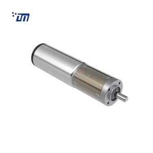
A φ32 mm-class DC planetary gear motor of the kind sized in the worked example.
Planetary Gear Motor Torque Calculation: FAQ
How do I convert kgf·cm to N·m?
Multiply by 0.0981. A gearbox rated 12 kgf·cm delivers about 1.18 N·m. Convert once at the start of the calculation and keep one unit throughout — mixing kgf·cm with N·m mid-calculation is the most common source of 10× sizing errors we see in RFQs.
What efficiency should I assume for a 2-stage or 3-stage micro planetary gearbox?
Use 90% per stage as a working value for metal-gear, grease-lubricated planetary stages — the same figures our gearbox datasheets publish: roughly 81% total for two stages, 73% for three, and 65% at four. If the datasheet states a single efficiency figure, ask which stage count and test speed it refers to before trusting it in a torque budget.
Can a 1:30 ratio be built in a single planetary stage?
Not in practice. Single micro planetary stages top out around 10:1; beyond that, tooth stresses, carrier loads and noise rise steeply. A 1:30 is built as two stages — for example 5:1 × 6:1 — which also keeps total efficiency near 81% instead of forcing a weak single-stage design.
Why is my measured output speed lower than the calculated value?
Two compounding reasons: the motor runs 10–15% below no-load speed at your working point, and manufacturing tolerances spread ratios by a few percent. Measure speed at the rated load with the gearbox warmed up, and if the shortfall exceeds about 15%, re-check the actual motor voltage under load — voltage sag narrows every margin at once.
Where to Go From Here
Run the three steps in order — load torque, ratio split, stage efficiency — then verify the peak case and the duty cycle before committing to a ratio. If you would rather have a second pair of eyes on the numbers, contact our engineering team with your load, speed and duty data, and we will return a sizing proposal with the calculation shown.