
Planetary Gear Motor vs Worm Gear Motor: When to Choose Which
A worm gearbox and a planetary gearbox can both turn a 3,000 rpm motor into a 20 rpm output shaft. On paper they look interchangeable. In the field they are not even close, and the difference shows up as heat, battery drain, or a machine that slowly creeps backwards down a slope after the power is cut.
We build both types at DongMing Motor — DC worm gear motors in the DM-46WM and DM-58WM families, planetary gear motors in the DM-36PM and DM-42PM families — so we have watched customers pick the wrong one in both directions. This article is the comparison we end up drawing on a whiteboard during those calls, with the numbers attached.
The one number that decides most of these projects
Efficiency is not a footnote here. It is the entire argument for most continuous-duty applications.
A planetary gearbox transmits torque through rolling contact. A worm gearbox transmits it through sliding contact — the worm thread literally slides across the worm wheel tooth face. Sliding contact throws away a large fraction of the input torque as heat, and the fraction gets worse as the reduction ratio gets steeper, because a steeper ratio forces a shallower lead angle.
That is the mechanism behind the table below. The worm efficiency figures are not a rule of thumb — they track the relationship η = tan γ / tan(γ + ρ′) from AGMA 6034 / ISO 14521, where the lead angle γ falls as the ratio rises. Our own DC worm gear motor datasheets follow the same curve — the DM-58WM555 is rated at roughly 50% gearbox efficiency in a 3-stage configuration and about 40% in the 4-stage configuration, because the 4-stage version reaches ratios like 548:1 and 1327:1 that leave almost no usable lead angle.
| Parameter | Planetary gear motor | Worm gear motor |
|---|---|---|
| Contact type | Rolling (multiple planet teeth share the load) | Sliding (single worm thread / wheel tooth pair) |
| Gearbox efficiency, typical | 90–96% single stage; 75–85% two stage | 85–90% at 10:1; 50–60% at 60:1+ |
| Efficiency vs ratio | Falls ~4–5 points per added stage | Falls steeply with ratio (lead angle effect) |
| Practical ratio range | 3:1 to ~2,000:1 (stacked stages) | 5:1 to ~1,300:1 in one right-angle housing |
| Torque per unit volume | Highest — 3–5× a same-diameter spur box | Moderate, but very high in a small right-angle envelope |
| Backlash, standard grade | ≤15 arcmin (1 stage), ≤20 arcmin (2 stage) | 40–90 arcmin typical; adjustable lower on request |
| Self-locking | No — needs a brake or an active hold current | Yes at ratios above roughly 30:1 |
| Shaft layout | Coaxial (input and output on one axis) | Right angle, 90° offset |
| Heat generated at full load | Low | High — the losses are thermal losses |
| Running noise (1 m, no load) | ≤55 dB | 55–62 dB, mostly low-frequency |
| Typical service life | ~20,000 h with grease-for-life | ~20,000 h; bronze wheel is the wear item |
| Relative cost for the same ratio | Higher | Lower in one stage |
Read that table with one application in mind and the choice usually falls out on its own. If you are sizing for a battery pack, efficiency is your runtime. If you are sizing a vertical actuator that has to hold a load with the power off, self-locking is your safety function.
Where the efficiency gap actually comes from
Three mechanisms account for nearly all of it.
Tooth count in mesh. A planetary stage meshes three, four or five planet gears against the sun and the ring at the same time, so the tangential load is divided across several contact lines. A spur stage has one tooth pair carrying everything. A worm set has one thread in contact, and that contact is a line sliding along the tooth.
Sliding velocity. In a worm set the sliding speed is a large multiple of the pitch-line speed — typically 3–8× depending on the lead angle. Friction power scales with sliding speed, which is why worm boxes run hot and why ISO VG220–VG320 oil, not grease, is usually specified in units above 20:1.
Duty point. Efficiency at rated torque is not efficiency at 20% torque. A planetary box that shows 94% on the datasheet may run at 88% in a real actuator cycle that spends most of its time at light load, because churning and bearing losses do not scale down with torque. The measurement methods behind those figures are standardised in IEC 60034-2-1. When we quote a gearbox for a mobile application we quote the efficiency at the actual duty point, not the peak figure.
Field example 1: a 24V AGV drive wheel
Application: a 60 kg payload AGV, two driven wheels, 125 mm diameter, required 0.55 m/s on a 3% floor incline, 8-hour shift, 24V DC bus.
Working backwards from 0.55 m/s at a 125 mm wheel gives roughly 84 rpm at the wheel. A 24V BLDC motor at 3,000 rpm needs a reduction around 36:1. Continuous torque at the wheel works out near 4 N·m per wheel including the incline component.
Option A — planetary, 2-stage 36:1, 94% gearbox efficiency. Required motor torque = 4 ÷ (36 × 0.94) = 0.118 N·m, so about 37 W at 3,000 rpm.
Option B — worm, 36:1 single-stage right angle, 62% efficiency at that ratio. Required motor torque = 4 ÷ (36 × 0.62) = 0.179 N·m, about 56 W at 3,000 rpm.
Same output, 51% more electrical power drawn, and every one of those extra watts turns into heat inside the gearbox. On an AGV that is roughly 2.5 hours off the battery run time and a much earlier thermal derate. For a mobile, continuous-duty drive, we recommend the planetary box and treat a worm drive as the wrong tool. The trade-off is real, though: a 2-stage planetary box in that size runs 60–90% more expensive than the equivalent worm reducer, and it needs a brake if the AGV parks on a ramp.
Field example 2: a 12V camera pole lift
Application: a 12 V CCTV pole with a 6 kg camera head on a 1.2 m lead screw, moving once or twice a day for 40 seconds, no power available during the idle state.
Here the duty cycle flips the answer completely. Total running time is under 15 minutes a day, so efficiency is almost irrelevant — even at 50% you are talking about a few watt-hours a month. What matters is that the load must not back-drive the nut down the screw when the relay opens.
A planetary box at 36:1 will happily back-drive. You would need either an electromagnetic brake (which draws current while holding, defeating the purpose) or a lead screw steep enough to self-lock, which a motor that small cannot turn. A worm gear motor at 36:1 with a single-start worm self-locks: the lead angle is below the friction angle, so the load cannot push the wheel backwards. Our DM-58WM555 4-stage series at 402:1 and 548:1 sits firmly in that region.
What you pay: 40% efficiency means the motor has to be oversized — which is why motor system efficiency is treated as a system-level design problem, not a component spec — and the box runs hot during those 40-second moves — we tell customers to keep the duty cycle under about 10% at rated torque for a 40.1 mm box so the oil temperature stays under 80 °C. If the application runs continuously instead of twice a day, the self-locking advantage stops compensating and the planetary box wins again.
When the right-angle layout decides it before efficiency does
There is a category of design where the argument never gets to efficiency, because the machine geometry rules out an inline drive. A pass-through conveyor with the motor mounted alongside the frame, a rotary cutting head where the shaft must exit at 90°, a lock actuator inside a 25 mm door cavity: no amount of planetary torque density helps if the output shaft points the wrong way.
Right-angle planetary and bevel-helical boxes exist, but they add a bevel stage that costs 3–5% efficiency and a significant amount of money. For ratios above 40:1 in a right-angle envelope, a worm box is usually the cheaper engineering answer even accounting for the losses.
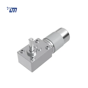
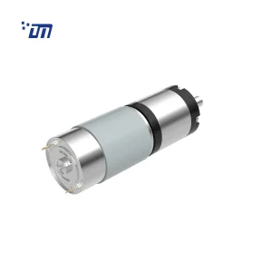
Our own product mix reflects this. The DM-58WM555 (40.1 mm gearbox width, 12–24 V, 2–122 rpm, 1–80 kgf·cm) exists because so many customers need a right-angle self-locking drive in a small housing. The DM-42PM series planetary gear motor exists because mobile and precision applications need the efficiency and the low backlash instead.
Backlash, stiffness and positioning
Worm drives are often described as low-backlash. That is true for a newly assembled, correctly shimmed worm box, and it stops being true after a few thousand hours because the bronze wheel wears. A planetary box made to a standard commercial grade holds ≤15 arcmin in one stage and ≤20 arcmin in two, and it stays there — gear wear in a hardened, ground planetary set is slow because the contact stresses are distributed.
If you are doing closed-loop positioning with an encoder, backlash is not just an accuracy number, it is a stability problem. Backlash acts as a dead zone inside the control loop, and a drive with 60 arcmin of lash will limit how high you can push the position loop gain. For how that lash is defined and measured, see gear backlash fundamentals. In most servo-ish applications that alone eliminates the worm option.
Thermal limits, which are usually the real rating
Gearbox ratings are thermal ratings more often than mechanical ones. A worm box that is mechanically rated for 30 kgf·cm at 40% efficiency is dumping 60% of the motor’s input power into its own housing, and the oil temperature is what actually limits the duty cycle. Keep worm oil below 80 °C; above that the film thins, friction rises further, and efficiency drops another few points — a feedback loop that ends in a seized wheel.
A planetary box with grease-for-life at 94% has almost no thermal problem at typical load levels, which is why the thermal derating question rarely comes up on those projects. If your application is continuous duty at rated torque and you find yourself calculating gearbox heat rejection, that is usually a signal that the gearing type is wrong, not that the gearbox is undersized.
Materials and what they cost over time
The worm pair is deliberately made from mismatched hardnesses: a case-hardened steel worm (20CrMnTi class, HRC 58–62) running against a phosphor bronze wheel (CuSn12Ni2, HB 95–115). The bronze sacrifices itself so the harder worm survives. That is good engineering, and it also means the wheel is a wear item — the most common major service event on an industrial worm box, typically after 6–10 years of continuous duty. A planetary set with hardened and ground alloy steel gears has no equivalent consumable.
Selection checklist
Answer these in order. The first four questions eliminate most of the field.
- Must the load hold position with the power off? Yes → worm (above roughly 30:1) or an added brake. No → either type is still open.
- Is there a right-angle layout constraint? Yes → weigh worm against an added bevel stage.
- What is the duty cycle at rated torque? Continuous above 30% → planetary. Intermittent below 10% → worm is usually fine and cheaper.
- Is the machine battery powered? Yes → the efficiency gap converts directly into run time; compute both options before deciding.
- What backlash can the control loop tolerate? Under 30 arcmin → planetary.
- Then check the boring things: available enclosure diameter and length, radial load on the output shaft, IP rating required, and whether you need a double output shaft (common on worm boxes, less so on planetary).
For the torque and ratio arithmetic behind these decisions, see our DC gear motor guide, and for the torque/speed/efficiency trade-off against spur gearing specifically, see planetary vs spur gear motors. If you are still at the architecture stage, what a planetary gear motor actually is is the better starting point.
Frequently asked questions
Is a planetary gear motor always more efficient than a worm gear motor?
Per stage, yes — 90–96% against 40–90% depending on ratio. But a fair comparison matches the whole reduction chain. A single 60:1 worm box at 62% will beat a 3-stage planetary equivalent at 3 × 4:1 if the planetary stages are badly matched or the planetary box is running far off its rated load. Match ratio, output speed and duty point before comparing efficiency numbers.
At what ratio does a worm gear motor become self-locking?
Self-locking depends on the lead angle, not directly on the ratio, but they move together: a single-start worm that gives a shallow lead angle typically self-locks above roughly 30:1. In practice the boundary sits between 20:1 and 30:1 and depends on the friction coefficient of the specific worm/wheel/lubricant combination, which is why a two-start worm at 20:1 may back-drive while a single-start at 20:1 holds. Ask for the self-locking condition at operating temperature, not at 20 °C.
Can I use a worm gear motor for continuous duty?
Yes, within its thermal rating, but size it on the continuous thermal rating rather than the peak torque. Because 40–50% of the input power turns into heat in the housing, a worm box that is comfortable at 10% duty will overheat at 100% duty at the same torque. We normally recommend synthetic PAO or PAG lubricant and a duty cycle under 30% at rated torque for compact worm boxes.
Which type gives lower noise?
Both are quiet at low speed. A planetary box measures ≤55 dB at 1 m no-load; a worm box runs 55–62 dB. The character differs more than the number: planetary noise is higher-frequency and rises with speed, worm noise is lower-frequency and dominated by sliding. If the machine sits next to a person, the worm box usually sounds less intrusive even at the same dB figure.
Do I need an encoder with either type?
Only if you need position or speed feedback. Note the interaction with backlash: with a 60 arcmin worm box, an encoder mounted on the motor shaft will report motion that has not yet reached the output shaft. Mount the encoder on the output when accuracy matters, or choose a low-backlash planetary box and put it on the motor.
{acf_post_brief}