
How to Read a Motor Datasheet: Stall Torque, No-Load Speed and the Rated Point
A gear motor datasheet contains three operating points that look interchangeable on paper but describe completely different machines: stall torque, no-load speed, and the rated point. Buyers who size a drive from the first two end up with a unit that overheats on the bench, loses speed once the load lands, and trips the supply during acceleration. This guide walks through every line on a DC gear motor datasheet, explains what each figure was measured under, and shows how to convert a real load into a specification you can actually quote.
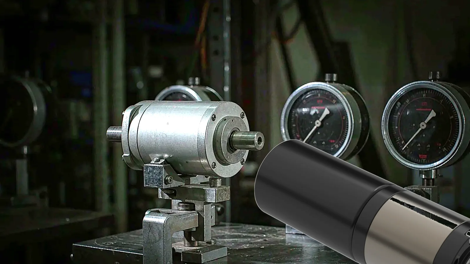
Datasheet numbers only describe one operating point; the drive has to be verified under a real load.
The Three Curves on Every Motor Performance Graph
Every DC gear motor datasheet reduces to a speed-torque line and two curves riding on it. Learn to read the shape once and you can compare any two suppliers in a few minutes.
The speed-torque line runs from no-load speed on the vertical axis down to stall torque on the horizontal axis. It is very nearly straight, and that straightness is the whole point: speed falls in proportion to load, so a drive quoted at 120 rpm without a load might deliver 96 rpm at its rated point and 0 rpm at stall.
The current line rises from no-load current at the top left to stall current at the bottom right. Current tracks torque almost exactly, because for a brushed DC or a brushless motor in current-control mode, torque is proportional to current: T = Kt × I. If you know the torque constant, you can predict the current draw at any load point without a test bench.
The efficiency curve arcs over the middle of the graph and peaks somewhere between 40% and 70% of stall torque — not at the rated point, and certainly not near stall. A planetary gear motor assembly typically peaks around 70–85% overall, with the gearbox contributing its own 90–95% per stage and the motor the rest. Chasing peak efficiency sounds sensible, but the peak sits at low torque and high speed, which is rarely where the load actually lives.
Here is how the three curves relate to the five operating points most datasheets label.
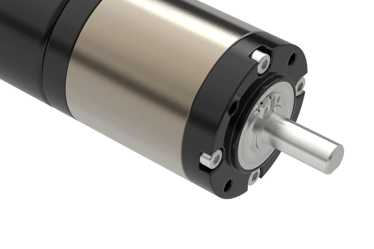
The rated torque on the label is measured at the output shaft — the gearbox, not the motor winding, is often the lower limit.
The Five Operating Points, and What Each One Was Measured Under
Most datasheets quote five numbers. They answer five different questions, and only one of them is a working torque.
| Operating point | Symbol on the sheet | What it actually means | Typical relationship to rated torque |
|---|---|---|---|
| No-load speed | n₀ | Speed at rated voltage with nothing on the shaft | Highest speed the drive will ever reach; not a working speed |
| No-load current | I₀ | Current needed to spin the rotor against internal friction only | Roughly 5–15% of rated current |
| Rated (continuous) torque | TN | Load the drive carries indefinitely without exceeding its thermal limit | 1.0× — this is the sizing basis |
| Peak (intermittent) torque | TP | Maximum torque for a stated short duration and repeat interval | 1.5–2.5× rated |
| Stall torque | TS | Torque at zero speed with full supply voltage across the winding | 3–5× rated for a brushed motor; can exceed 5× after a high-ratio gearbox |
The gap between rated and stall torque is the single most misread figure on the sheet. A brushed DC motor’s stall torque typically lands at three to five times its rated torque, because stall current is limited only by winding resistance and brushes. On a geared unit the multiplication looks even more dramatic, which is exactly why engineers get caught: the gearbox ratio multiplies torque, but the gearbox’s own rated output torque caps the result far below the arithmetic figure.
A 100:1 gearbox with 0.3 N·m of motor torque does not deliver 30 N·m. At 80% efficiency it delivers about 24 N·m on paper — and if that gearbox frame is rated for 15 N·m of output torque, the real limit is 15 N·m. The lower of the two governs, always.
Why No-Load Speed Is the Wrong Number to Design Around
No-load speed is the easiest figure to grab and the most expensive one to get wrong. It describes a motor doing nothing.
Every datasheet speed comes with a condition attached: measured at a stated voltage, at a stated ambient temperature, and at a stated load. Strip the condition off and the number is meaningless. A 24V unit tested at 25 °C tells you nothing about the same drive at 12V, and a drive rated for a 40 °C ambient will derate once it sits inside a sealed enclosure at 60 °C.
In practice, design speed is roughly 75–85% of no-load speed for a well-matched gear motor. If your mechanism needs 100 rpm at the output shaft under load, specifying a drive whose no-load speed is 100 rpm guarantees you will fall short. Pick a unit whose no-load speed sits at 120–135 rpm so the operating point lands near the efficient middle of the curve.
This is also where the gearbox ratio enters. The relationship is Tout = Tmotor × i × ηg for torque and nout ≈ nmotor / i for speed, where i is the reduction ratio and ηg the gearbox efficiency. Ratio multiplies torque and divides speed, but the published gearbox torque limit still takes priority over the calculated value. Our range of high-torque DC planetary gear motors is specified by output-shaft torque for exactly this reason — the number you compare is the number the gearbox can survive.
Terminology here is worth checking per supplier. Some sheets say “rated torque,” others “nominal torque,” “continuous torque,” or “maximum continuous torque.” The definition varies, so the test voltage, ambient temperature, duty cycle, and allowable winding temperature all need to be on the sheet before you can compare two suppliers fairly.
Reading the Electrical Parameters Without Getting Burned
Torque figures dominate the buying decision, but the electrical lines decide whether the drive survives its first week.
Stall current is the most important number that never appears in a headline. For a brushed motor it is approximately supply voltage divided by armature resistance, Istall ≈ V / Rarmature. On a 24V motor with a 2 Ω winding that is 12 A at the instant of stall, and the driver has to survive it. Check three things on the controller: continuous output current, peak output current, and the current-limiting method.
Copper loss rises with the square of current. Going from 5 A to 8 A multiplies I²R loss by 2.56, not 1.6. That squared relationship is why a motor tolerates a two-second overload and dies from a two-hour one. It is also why a driver that limits current to 10 A cannot deliver the peak torque the motor’s curve promises at 18 A.
Winding insulation class caps everything else. A Class B winding is limited to 130 °C hot-spot temperature and a Class F winding to 155 °C, per the IEC 60085 insulation thermal evaluation standard. Those limits, not the torque curve, set the continuous rating. If the sheet does not state the insulation class, ask.
Terminal resistance is a cold number. A datasheet resistance is measured at 25 °C. Copper resistance rises about 0.4% per °C, so a winding sitting at 100 °C has roughly 30% more resistance than the sheet says, which cuts stall current accordingly. With graphite brushes, resistance is also load-dependent, so the advertised figure only holds at high currents.
The Datasheet Fields That Decide the Duty Cycle
Continuous torque is a thermal rating wearing a mechanical label. Three fields on the sheet determine whether you can use it continuously.
Duty cycle. If your application runs 30 seconds on, 90 seconds off — a duty cycle of 25% — the winding has time to shed heat between cycles and the motor can carry more than its continuous rating for the “on” portion. Run the same drive continuously at the same torque and it will cook. Sheets that state only “intermittent” without an on/off ratio are telling you nothing you can calculate with.
Thermal resistance. Expressed in K/W, thermal resistance from winding to housing and housing to ambient defines the temperature rise at a given power loss. A metal frame bolted to a heat-conducting mounting can shed heat dramatically better than the same motor on a plastic panel; the mounting is part of the thermal path, and the datasheet usually assumes free air.
Zero-speed holding. Holding a load at standstill is not the same as stall, and it is not free. The drive produces torque at zero speed with no back-EMF to oppose the supply, so current and heat both peak. If your actuator must hold position for several minutes — a valve, a clamp, a gate latch — specify the holding time separately and check it against the thermal limit. This is the case where comparing stall torque alone gives a confidently wrong answer.
| Duty pattern | What to check on the sheet | Practical limit |
|---|---|---|
| Continuous, ≥30 min holds | Rated (continuous) torque + ambient temperature | Design load ≤ rated torque |
| Cyclic, 25% duty or lower | Rated torque + duty ratio + winding class | Rated torque × a factor set by the cooling interval |
| Short bursts (<2 s acceleration) | Peak torque + its stated duration and repeat interval | Peak torque, provided the driver can supply its current |
| Zero-speed holding | Holding torque + holding time + thermal resistance | Set by temperature rise, not by stall torque |
How to Check a Datasheet in Five Minutes
Most bad selections are visible on the sheet before a sample ships. Run these five checks in order and you will eliminate the candidates that cannot work.
- Confirm the torque is rated, not stall. Find the figure the sheet labels rated, nominal, or maximum continuous. If the only torque number published is stall torque, treat the sheet as incomplete and request the continuous rating.
- Confirm the speed is quoted at load. A speed with no load condition attached is a no-load figure. Match it against your required output speed using the 75–85% rule above.
- Confirm the current is within the driver’s limit. Compare rated current against your controller’s continuous rating and stall current against its peak rating and current-limiting behaviour.
- Confirm the duty cycle and ambient temperature are stated. No stated condition means no comparable rating, regardless of how precise the number looks.
- Confirm the gearbox output rating exceeds your calculated output torque. Motor torque × ratio × efficiency gives the theoretical output; the gearbox catalogue rating gives the physical ceiling. Take the lower one.
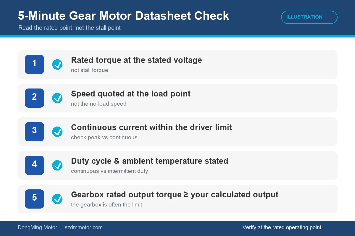
A five-point pass before you shortlist a gear motor. (Illustration)
While you are on the sheet, check the mechanical lines too. Backlash is quoted in degrees or arcminutes and matters for positioning work; anything above 1° of backlash will show up as visible lost motion on a reversing axis. Radial and axial shaft load ratings are separate from transmitted torque, and a belt or chain drive can exceed them even when the torque figure looks comfortable. Then confirm the mounting interface, IP rating, and lubrication service interval against the IEC 60529 ingress protection classification standard if the unit runs in dust or washdown conditions.
A Worked Example: 24V Planetary Gear Motor for a 48 kg Chassis
Numbers on a datasheet only become a decision when you push a real load through them. Here is the sizing sequence we run with customers.
Step 1 — convert the load to torque at the wheel. A 48 kg four-wheel platform on 125 mm wheels, drive force 180 N. Torque at each of two driven wheels = (180 N × 0.0625 m) / 2 = 5.63 N·m (≈57 kgf·cm) per wheel. Add 25% for rolling-resistance variation and surface change, and the target is 7.0 N·m (≈71 kgf·cm).
Step 2 — convert wheel torque to output-shaft torque. With a 1:1 wheel coupling the gearbox output must supply 7.0 N·m continuously during a climb.
Step 3 — work backwards to the motor. Choosing a 24V planetary unit with i = 100:1 and η = 0.80, the required motor torque is 7.0 / (100 × 0.80) = 0.0875 N·m. That is the continuous torque the motor winding must deliver, and it is the figure to look up — not stall torque.
Step 4 — check speed. Required ground speed 0.9 m/s at 125 mm wheel diameter gives 0.9 / (π × 0.125) × 60 ≈ 137 rpm at the wheel, so the motor must turn at 13,700 rpm — well above a typical 24V small DC motor’s usable range. The realistic fix is a lower ratio with a larger wheel, or a higher-torque motor at a lower ratio. That iteration is normal; the first ratio you try rarely survives step 4.
Step 5 — check the two limits that are not torque. Stall current at 24V and 1.8 Ω winding resistance is roughly 13 A, which the driver must survive at every start. And the continuous 7.0 N·m has to sit below the gearbox’s rated output torque, not below motor torque × ratio.
This example is a common field scenario for us, and it is where the datasheet habit pays off. Customers who sized from stall torque pick a drive that looks like it has four times the margin needed, then find it stalls on a 12% ramp because the rated point was never checked. The same failure pattern shows up in how gear motor noise and vibration are actually measured — the bench number and the field number diverge as soon as the real load and the real mounting enter the picture.
Five Mistakes That Repeat Across Nearly Every Project
Sizing from stall torque. The most common and most expensive error. Stall torque is a zero-speed limit for jams and end stops, not a working point. Design on the continuous figure, then verify the peak separately.
Treating no-load speed as working speed. Expect a 15–25% drop to the loaded operating point. Building a speed spec on the no-load column guarantees a slow machine.
Ignoring the gearbox torque ceiling. Motor torque multiplied by ratio is a theoretical figure. The gearbox catalogue rating is a physical one. Gear teeth, output bearings, and shaft diameter set the real limit, and exceeding it fails the gearbox long before the motor notices.
Overlooking shaft and reaction loads. Radial load from a belt, axial load from a lead screw, and the reaction torque from a fast start all load the gearbox in ways a torque figure does not capture. Add a shaft-load check to every selection.
Assuming the peak is available from the drive electronics. A controller limited to 10 A cannot deliver a torque that requires 18 A, however generous the motor’s peak line looks. Check the driver before the motor on peak-demand applications.
FAQ
Should I size a gear motor from stall torque or rated torque?
Size from rated (continuous) torque at your target speed. Stall torque is the zero-speed maximum the motor produces when the shaft cannot turn, and sustained stall current will damage the winding within seconds to minutes. Use stall torque only to size the driver’s current handling and to check jam and end-stop conditions.
Why does my motor reach the rated torque briefly and then overheat?
Because the rated figure is heat-limited, not strength-limited. Copper loss rises with the square of current, so a load 50% above rated raises winding loss by about 2.25 times. If the duty cycle gives the winding no cooling interval, the temperature keeps climbing and eventually exceeds the insulation class limit.
What is the difference between rated torque and peak torque?
Rated torque is the load the drive carries indefinitely within its thermal limit. Peak torque is the maximum available for a stated short duration and repeat interval, typically 1.5–2.5 times rated, and it is meaningful only when the datasheet states the duration. A peak value with no duty cycle attached should not be treated as a rating.
Can I trust the torque on a gear motor product page without a datasheet?
Rarely. Product pages usually publish stall torque because it is the largest number, and they often omit the load condition, duty cycle, and ambient temperature. Ask for the rated torque at a stated voltage, the gearbox rated output torque, and the winding insulation class before comparing quotations.
Does a higher gear ratio always give more usable output torque?
No. Torque rises with ratio up to the gearbox’s rated output torque, then stops — additional stages add mesh losses and mechanical stress without adding usable torque. On a 12V micro gear motor platform, a 100:1 unit and a 1,000:1 unit may differ by far less than ten times in rated output torque.
Closing the Loop Before You Order
A DC gear motor datasheet is a set of operating points, not a set of promises. Read the rated line first, attach the load condition and duty cycle to every speed figure, confirm the gearbox output rating caps the arithmetic, and verify the driver can supply the current the curve implies. Do those four things and the unit that arrives will behave like the unit on the sheet.
If you are working through a selection and the datasheet you have does not publish a continuous torque at your operating voltage, send the application details — load torque, output speed, duty cycle, ambient temperature, and supply voltage — to our engineering team and we will size it against a real curve rather than a headline figure. For the wider process, our motor selection guide covers how gear ratio, voltage, and thermal margin interact, and how gear ratios are matched to a load walks through the sizing maths in more depth.
By the DongMing Motor engineering team. We manufacture DC planetary, worm, spur and square gear motors plus brushless DC motors in frame sizes from φ10 mm to φ63 mm, and test every production batch with a 100% no-load current check plus sampled rated-load continuous running. See our quality control process for the test sequence.