
BLDC Planetary Gear Motor: Types, Features, and Functions
A BLDC planetary gear motor combines a brushless DC motor with a planetary gearbox. The combination is a compact, high-torque power transmission unit used across automation, robotics, medical equipment and smart home devices.
The motor itself uses electronic commutation instead of brushes, so there is no brush or commutator to wear out. That removes the single most common maintenance item in a small DC drive and is the reason these units are specified where a machine has to run for years without service.
The gearbox consists of a central sun gear, several planet gears and an outer ring gear. The sun gear is driven by the motor rotor, the planet gears engage both the sun and the ring, and the carrier output turns at a speed set by the tooth counts. Because the load is shared across three or more planet gears at once, a planetary stage carries far more torque than a spur stage of the same diameter. That is what makes the format useful in machines with tight space and weight limits.
The frame sizes we build run from 22 mm to 56 mm, and the ratio range covers light positioning duties through to high-torque lifting. Typical uses include BLDC planetary gear motors, smart home equipment, robotics, CNC machines, surveillance systems and general automation equipment.
This page covers the three things the title promises: the types you can specify, the features that decide whether a BLDC planetary unit beats another architecture, and the functions performed by the integrated driver.
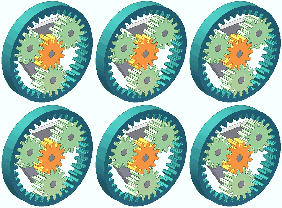
Types of BLDC planetary gear motors
Four decisions define the unit you end up with. They are largely independent, so a 36 mm four-stage unit with an integrated driver and an encoder is a perfectly normal specification.
By gear stage count and reduction ratio
Each planetary stage multiplies the ratio, and each stage also removes efficiency. The trade-off is the single most common specification mistake: builders ask for the highest ratio available and then wonder why the output torque is lower than calculated.
| Stage count | Typical ratio | Gearbox efficiency | When to use it |
|---|---|---|---|
| Single stage | 3.7:1 – 5.2:1 | ≈ 90% | Highest efficiency; use whenever one stage reaches the target output speed |
| Two stage | 14:1 – 27:1 | ≈ 81% | The usual compromise for mid-range ratios |
| Three stage | 51:1 – 139:1 | ≈ 73% | High ratio, still usable for continuous duty |
| Four stage | 189:1 – 721:1 | ≈ 66% | Very high ratio; check the torque budget before choosing it |
| Five stage | 977:1 – 2418:1 | ≈ 59% | Slowest output; efficiency loss is significant, so confirm the motor can carry it |
Across our range the ratios run from 3.7:1 on a single stage up to 2418:1 at five stages. The figures above are typical values measured across the frame sizes, so the exact set of ratios available depends on the model — a 22 mm unit and a 36 mm unit do not offer identical steps. Five stages costs you roughly 59% gearbox efficiency against 90% for a single stage, so specify the smallest stage count that reaches your output speed.
By rotor position feedback
How the driver knows where the rotor is decides the cable count, the low-speed behaviour and the cost.
- Hall sensor feedback. Three Hall devices read the rotor magnets and give six commutation states per electrical revolution. It is the default for speed control and for anything that must start under load. This is what most of our integrated-driver units use.
- Sensorless (back-EMF). No Hall sensors, so fewer wires and a cheaper motor. The driver infers rotor position from the voltage the spinning magnets induce in the idle winding. It works well for fans and pumps, but starting from standstill under a heavy load is unreliable, which rules it out for lifting and positioning duties.
- Encoder feedback. A magnetic or optical encoder adds a resolution far finer than a Hall state, which is what closed-loop position control needs. Specify this only when the machine has to hold or reach a position, not when it only has to turn at a set speed. Hall effect sensors vs encoders covers the crossover point in detail.
By driver integration
This one changes your wiring harness and your engineering workload more than any other choice.
- Integrated (built-in) driver. The electronics sit inside the motor housing or the rear cap. You supply DC power and a few control signals, and the unit is a complete drive. It shortens the design cycle, but the driver is now inside the thermal envelope of the motor, so ambient temperature matters. The next section explains each control wire.
- External driver. You receive a bare three-phase BLDC motor with Hall outputs and pair it with your own controller. This suits machine builders who already have a drive platform, need a specific control loop, or want the electronics in a separate enclosure away from heat.
By gearbox frame size
The smallest frame that carries your torque is usually the right one, because a larger gearbox costs more, weighs more and needs more space without improving efficiency. The current range covers seven diameters and nineteen models:
| Gearbox diameter | Models | Count |
|---|---|---|
| 22 mm | DM-22PBL2230 | 1 |
| 24 mm | DM-24PBL2418, DM-24PBL2430 | 2 |
| 28 mm | DM-28PBL2838, DM-28PBL2847 | 2 |
| 36 mm | DM-36PBL3626, DM-36PBL3630, DM-36PBL3640, DM-36PBL3650, DM-36PBL3657 | 5 |
| 42 mm | DM-42PBL4260, DM-42PBL4266, DM-42PBL4275 | 3 |
| 52 mm | DM-52PBL5067, DM-52PBL5074, DM-52PBL5086 | 3 |
| 56 mm | DM-56PBL5074, DM-56PBL5086, DM-56PBL5772 | 3 |
Full specifications, drawings and ratio tables for each model are listed in the BLDC planetary gear motor category.
Features: how a BLDC planetary gear motor compares
No architecture wins on every line. The table below is the honest comparison, and the value ranges are typical rather than fixed, because a well-built brushed unit will beat a poorly built brushless one.
| Property | BLDC + planetary | Brushed DC + planetary | AC induction + gearbox | Stepper + gearbox |
|---|---|---|---|---|
| Typical efficiency | 75–90% | 60–75% | 50–70% | 50–70% |
| Service life, continuous duty | 5,000–20,000 h | 500–3,000 h, brush-limited | 20,000 h+, bearing-limited | 5,000–20,000 h |
| Speed control range | Wide, closed loop | Wide, open loop on voltage | Narrow without a VFD | Narrow usable band, resonance zones |
| Torque at low speed | High | High | Moderate | Falls off as speed rises |
| Noise and vibration | Low to moderate | Moderate to high, brush noise | Low | High near resonance |
| Routine maintenance | Bearings only | Brush replacement | Bearings only | Bearings only |
| Control electronics | Driver required, often integrated | Simple PWM is enough | VFD required | Driver required |
| Relative unit cost | Higher | Lowest | Moderate | Moderate |
Three of these rows decide most projects:
- Efficiency at part load. A BLDC drive keeps most of its efficiency when the load drops, because the driver can advance or retard commutation timing. A brushed motor loses efficiency as soon as the operating point moves away from its design point, which matters on battery-powered equipment where every percentage point becomes runtime.
- Life under continuous duty. This is the one row where the gap is structural rather than incremental. Brush wear is a consumable, so a brushed unit’s life is counted in hundreds to low thousands of hours regardless of how good the gearbox is.
- Control electronics. A BLDC motor is never a drop-in replacement for a brushed one, because it cannot run from a plain DC supply. If the machine has no controller and no space to add one, the integrated-driver variant is usually what makes the switch practical.
The planetary gearbox contributes its own set of features on top of the motor: high torque density in a short axial length, low backlash when specified, and quiet running compared with a spur or worm stage of similar ratio. If unit cost is the binding constraint rather than size or noise, planetary vs spur gear motor explains where a spur gearbox still wins.
Why is a BLDC planetary gear motor’s lifespan longer than a brushed one?
BLDC planetary gear motors have gained significant popularity in various industries due to their numerous advantages over brushed planetary gear motors. One of the key advantages is their longer lifespan, which depends on the gear design’s architecture.
Brushless DC motors (BLDC motors) are invented with a different arrangement compared to brushed motors. The brush and rotor create friction in the planetary brush gear motor that limits the motor’s lifespan to a few hundred hours, unlike the brushless motor, which produces less friction, thereby having an extended lifespan. DC brushless motors can typically operate for thousands of hours before requiring maintenance or replacement, making them highly reliable and cost-effective in the long run.
Using electronic commutation, Brushless DC gear motors don’t need brushes and commutators. Instead of brushes, BLDC motors incorporate a controller that precisely controls the switching of current to the motor windings. This electronic commutation reduces friction and wear, allowing for smoother operation and increased efficiency.
Furthermore, the brushless design offers other benefits contributing to the extended lifespan. With fewer mechanical components, fewer points of failure result in enhanced durability. Additionally, the electronic commutation system enables better control over the motor, reducing stress on the gears and ensuring smoother and more efficient power transmission.
To recap, BLDC planetary gear motors outperform their brushed counterparts in terms of lifespan due to the utilization of brushless DC motors. Eliminating brushes and adopting electronic commutation significantly reduce wear, increase efficiency, and improve overall reliability. This makes brushless planetary gear motors a preferred choice in applications where longevity and consistent performance are essential.
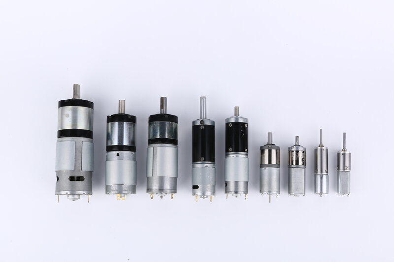
How BLDC planetary gear motor built-in driver works?
A BLDC planetary gear motor is a compact and efficient motor whose torque output is high and offers smooth operation and precise control. The motor is driven by a built-in driver, which plays a crucial role in its operation.
The built-in driver of a BLDC planetary gear motor controls the motor’s speed, direction, and other parameters. It receives power through the power supply cables consisting of positive (+) and negative (-) terminals. These cables provide the necessary voltage and current for the motor’s operation.
The signal feedback cable transmits information about the motor’s rotational speed, position, and other feedback data. This feedback helps the driver adjust and optimize the motor’s performance.
The direction control cables, often called CW (clockwise) and CCW (counterclockwise), enable the driver to change the motor’s rotational direction while the PWM control cable allows the driver to modulate the motor’s speed by adjusting the pulse width modulation signal. By controlling the current flow through these cables, the driver can determine the desired direction of rotation and regulate the motor’s speed.
Lastly, the brake control cable is responsible for activating the brake mechanism in the motor. When the brake control signal is applied, the motor stops quickly and securely.
To sum it up, the built-in driver of a BLDC planetary gear motor integrates these cables to provide precise control and efficient operation, making it a versatile choice for various applications.
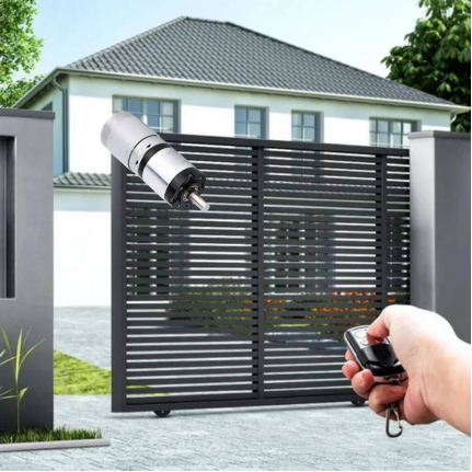
Choosing between a BLDC planetary gear motor and other architectures
A BLDC planetary gear motor is the right answer when you need high torque in a small diameter. It is not automatically the right answer for every drive. Two comparisons decide most projects:
- Against a brushed DC gear motor: a brushed unit costs less up front, but brush wear limits life, and the planetary gearbox behind it does not change that. If the machine is expected to run for thousands of hours, the brushless version pays for itself in service calls.
- Against a spur gear motor: a spur gearbox is cheaper and easier to source, but it is louder and longer end to end. Planetary wins on torque density and noise; spur wins on unit cost.
On the electronics side, position feedback is usually the next decision. Hall effect sensors vs encoders covers when a simple Hall arrangement is enough and when you need a real encoder. If the goal is longer service life rather than more torque, extending brushless motor lifespan is the more useful place to start than a bigger motor.
The sizes we tool for range from 22 mm up to 56 mm, and the BLDC planetary gear motor range lists them by frame size and ratio. Reduction ratios run from 3.7:1 on a single stage up to 2418:1 at five stages — but note that five stages costs you roughly 59% gearbox efficiency against 90% for a single stage, so specify the smallest stage count that reaches your output speed.
How to specify one in five steps
Most quotation delays come from a specification that is missing one of these five numbers. Working through them in order avoids it.
- Output speed. State the rpm at the gearbox shaft, not the motor. Everything else follows from this and from the load.
- Output torque, including the service factor. Give the continuous and the peak torque separately. A load that only peaks briefly during a jam should not be sized as continuous, but it must not stall the motor either.
- Duty cycle and expected life. Continuous, intermittent with a stated on/off ratio, or occasional. A continuous duty requirement is what pushes a project from brushed to brushless.
- Supply voltage and available current. A 24 V rail with a 2 A budget describes a very different motor from a 24 V rail with 10 A. If the unit is battery powered, the cut-off voltage matters as much as the nominal one.
- Environment and mounting. Ambient temperature, IP rating, shaft load and space envelope. Ambient temperature is especially relevant for integrated-driver units, since the electronics sit inside the motor.
With those five, the frame size and stage count can be fixed, and the remaining choices are feedback type and driver integration. If the application is an outdoor or washdown environment, confirm the IP rating before fixing the driver position, because an external driver is easier to protect than an integrated one.
Related reading
Product Application
Heat pump air conditioners
Commercial air conditioners
Solution Features
1.High-efficiency flux-weakening control technology reduces reactive power consumption and improves energy efficiency;
2.Adaptive torque compensation technology ensures smoother operation;
3.Bus voltage ripple suppression algorithm minimizes bus voltage ripple;
4.Isolated 485 communication for safe and reliable operation;
5.Integrated filter board, capacitor board, and frequency conversion module board reduce overall wiring and simplify installation procedures.
6.Supports two drive modes:
1.1.Built-in drive type BLDC fan: Can be directly controlled via PWM signal (fan has built-in control board, no external drive algorithm required).
1.2.External drive type brushless DC motor: Some models can be directly driven (motor has no built-in control board, relies on drive board’s complete commutation and power output functions).
7.Heat sink can be customized to air cooling or refrigerant cooling according to customer requirements.
#wptmtable11 .dataTables_wrapper > .dataTables_scroll {max-height:500px;overflow: auto;}window.wptm_ajaxurl = ‘https://szdmmotor.com/wp-admin/admin-ajax.php?juwpfisadmin=false&action=Wptm&’; window.wptm_front = ‘https://szdmmotor.com/wp-content/plugins/wp-table-manager/app/site/assets/’; window.wptm_style = ‘https://szdmmotor.com/wp-content/uploads/wptm/’;