
Micro DC Motor Sizing Guide: Selecting the Right Voltage, RPM, and Torque for Compact Devices
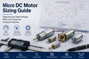
Selecting a micro DC motor for a compact device is not simply a matter of matching voltage or choosing the highest RPM available. Engineers need to balance motor voltage, operating speed, output torque, gear ratio, current consumption, mechanical load, and duty cycle within strict space constraints.
This guide provides a practical micro DC motor sizing method for engineers designing compact automation equipment, smart devices, medical equipment, robotics, and consumer electronics.
Table of Contents
- Start With the Mechanical Load
- How to Select Micro DC Motor Voltage
- How to Calculate Required RPM
- How to Determine Motor Torque
- Choosing the Right Gear Ratio
- Current, Efficiency, and Thermal Considerations
- Practical Micro DC Motor Selection Example
- FAQ
1. Start With the Mechanical Load
The first step in micro DC motor sizing is determining what the motor actually needs to move.
For rotary applications, engineers should identify:
- Required output torque
- Required output speed
- Load inertia
- Friction and mechanical resistance
- Acceleration time
- Operating cycle and duty cycle
- Available installation space
For applications such as micro gear motors for smart locks, robotic joints, electric curtains, valves, pumps, and small actuators, the required torque is often more important than no-load motor speed.
A practical design should include a safety factor. For many compact mechanisms, a starting point of approximately 1.3–2.0× the calculated continuous load torque is reasonable, although the actual factor depends on load variation, friction uncertainty, acceleration requirements, and reliability targets.
2. How to Select Micro DC Motor Voltage
Common micro DC motor operating voltages include 3V, 6V, 12V, and 24V, with lower-voltage motors frequently used in battery-powered products.
Voltage selection should be based on the available power source and the motor’s electrical characteristics rather than torque requirements alone.
For a simplified DC motor model:
V ≈ I·R + Ke·ω
where:
- V= applied voltage
- I= motor current
- R= winding resistance
- Ke= back-EMF constant
- ω= rotational speed
Increasing voltage generally increases available speed, but excessive voltage can increase current, winding temperature, brush wear, and mechanical stress.
For a 3V micro DC motor, for example, the engineer should verify not only rated speed but also startup current, stall current, continuous operating current, and thermal performance.
Long-tail keywords: how to choose micro DC motor voltage, 3V micro DC motor selection, 6V micro DC motor for compact devices, low voltage DC motor sizing.
3. How to Calculate Required RPM
The required output RPM should be calculated from the mechanism’s actual movement.
For a wheel or pulley with diameter D:
RPM = 60v / (πD)
where:
- v= required linear velocity
- D= wheel or pulley diameter
For screw-driven mechanisms, the relationship can be estimated from screw lead:
RPM = 60v / L
where L is the linear distance traveled per revolution.
This is particularly useful when selecting a micro gear motor for linear actuators, electric blinds, automatic locks, or compact positioning systems.
Remember that gearbox output speed—not the bare motor’s no-load RPM—is normally the key specification.
4. How to Determine Required Motor Torque
The required output torque can be estimated from the mechanical load.
For a tangential force applied at radius r:
T = F × r
For lifting applications:
T = F × r
where F is the load force and r is the effective pulley radius.
For acceleration-sensitive applications, engineers should also consider inertia:
T_total = T_load + Jα
where:
- J= rotational inertia
- α= angular acceleration
This is important for micro gear motors used in robotics and precision mechanisms, where a motor may need substantially more torque during acceleration than during steady-state operation.
A common mistake is selecting a motor based only on its stall torque. Stall torque is a maximum condition and should not normally be treated as the continuous operating torque.
5. Choosing the Right Gear Ratio
When the motor itself cannot provide sufficient torque at the required speed, a gearbox can trade speed for torque.
A simplified relationship is:
T_out ≈ T_motor × i × η
where:
- T_out= gearbox output torque
- T_motor= motor torque
- i= gear ratio
- η= gearbox efficiency
For example, if a motor produces 0.02 N·m and a 50:1 gearbox has 70% efficiency:
T_out ≈ 0.02 × 50 × 0.70 = 0.70 N·m
In real designs, engineers should also consider gearbox backlash, gear strength, bearing load, noise, efficiency, and service life.
This is why micro planetary gear motors are often selected for applications requiring high torque density, while spur gearboxes can be attractive when cost and compactness are the primary priorities.
Long-tail keywords: micro DC gear motor torque calculation, micro planetary gear motor for high torque, small DC gear motor speed and torque selection.
6. Current, Efficiency, and Thermal Considerations
A motor that meets the torque and RPM requirements may still fail because of excessive temperature rise.
Engineers should check:
| Parameter | Why It Matters |
| No-load current | Indicates basic motor losses |
| Rated current | Useful for continuous operation |
| Stall current | Determines driver and startup requirements |
| Rated torque | Main continuous operating reference |
| Stall torque | Maximum theoretical torque |
| Motor efficiency | Influences battery life and heat |
| Duty cycle | Determines thermal loading |
For battery-powered products, electrical efficiency is particularly important.
A motor operating near stall can draw several times its normal operating current. Therefore, the motor driver, PCB traces, battery, connectors, and power supply must all support the transient current.
For compact housings, thermal analysis is also important because there is limited surface area for heat dissipation.
7. Practical Micro DC Motor Selection Example
Suppose an engineer is designing a compact actuator with:
- Required output speed: 30 RPM
- Required continuous torque: 25 N·m
- Available supply: 6 V
- Required compact gearbox
- Intermittent operation
A reasonable initial target is to select a geared motor with approximately:
- 6 V rated voltage
- 30 RPM rated output speed
- ≥0.35–0.50 N·m rated/usable torque, depending on the actual safety margin and duty cycle
- Stall torque significantly above the maximum expected transient load
- Current compatible with the motor driver and battery
The final selection should then be validated through load testing, temperature-rise testing, startup testing, endurance testing, and voltage variation testing.
For production applications, the motor should be evaluated under the real mechanism rather than tested only under a laboratory no-load condition.
8. Key Selection Checklist
Before choosing a micro DC motor for a compact device, confirm these parameters:
- What is the required output RPM?
- What is the continuous load torque?
- What is the peak or startup torque?
- What voltage is available?
- What is the maximum allowable current?
- What gearbox ratio is required?
- What is the acceptable motor and gearbox size?
- What is the duty cycle?
- What temperature rise is acceptable?
- What are the required lifetime and noise limits?
The best motor is therefore not necessarily the motor with the highest torque or RPM. It is the motor that provides the required speed and torque at the required voltage while maintaining acceptable temperature, efficiency, size, noise, and service life.
FAQ
What voltage is best for a micro DC motor?
There is no universal best voltage. 3V, 6V, 12V, and 24V micro DC motors are selected according to the system power architecture. Battery-powered products often favor lower-voltage motors.
How do I calculate the required torque for a micro gear motor?
Calculate the mechanical load torque first, then account for acceleration, friction, and a suitable safety factor. For a simple radial load, torque is approximately force × radius.
Should I select a motor based on stall torque?
No. Stall torque should be used as a limit/reference, not as the normal continuous operating point. Continuous torque, temperature rise, and duty cycle are more important for reliable operation.
When should I use a micro planetary gear motor?
A micro planetary gear motor is a strong choice when the application requires high torque density, compact dimensions, good load distribution, and relatively high gearbox strength.
How much safety margin should a micro DC motor have?
A preliminary engineering design often starts around 1.3–2.0× the calculated continuous torque, but the appropriate margin depends on load variation, acceleration, gearbox efficiency, environmental conditions, and expected lifetime.