
Gear Motors for Vending Machines and Dispensers: Torque, Duty Cycle and Delivery Mechanism Selection
Gear motors sit at the center of every vending machine and self-service dispenser, yet most machine builders still specify them by copying the previous model’s part number. That habit works until a heavier product line, a colder cabinet, or a longer delivery spiral quietly pushes the drive past its stall point — and then you get the two complaints that dominate vending service logs: jams and burned-out drives.
This guide breaks the selection problem into the five decisions that actually determine reliability: which mechanism the motor drives, what torque the dispense action really needs, how the vend cycle shapes the duty rating, whether the mechanism can back-drive the motor, and how noise and environment constrain the gearbox. The numbers used here are typical values for small DC gear motors in the 12–42 mm class; verify every value against your own load before locking a design.
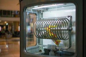
The Five Drive Points Inside a Vending Machine
A fully featured machine uses one gear motor per function, and each function stresses the gearbox differently:
| Drive point | Motion | Typical output speed | Load character | Key risk |
|---|---|---|---|---|
| Spiral product lane | Rotate coil 1 revolution per vend | 5–30 rpm | Medium torque, brief stall on jam | Coil jam, stall burnout |
| Spring-loaded snack lane | Turn spring 1–2 turns | 10–40 rpm | Light-to-medium torque | Spring override at high speed |
| Pusher plate | Reciprocate 200–300 mm | 15–45 rpm | Medium, rising with payload | Binding at full payload |
| Elevator / lift delivery | Raise carrier 300–800 mm | 3–10 rpm | Highest torque, holding required | Back-driving, cable shock |
| Dispensing door or flap | Rotate 60–90° | 20–60 rpm | Very light, high cycle count | Gear wear from frequent starts |
Three observations from service data across machine generations:
- The spiral lane and the elevator dominate warranty claims. They carry the real payload; the flap and spring mechanisms rarely fail electrically.
- Stall is a normal event, not a fault. A can wedged in a coil must be treated as a design condition: the drive must survive a full-voltage stall for the time it takes the controller to detect overcurrent and cut power — typically 0.5–2 s.
- Cycle counts are lower than people assume but starts are brutal. A busy machine might vend 80–150 times a day, but every start is from standstill at full load, which is exactly where gear motors see peak current and peak gear-tooth stress.
Torque: What a Vend Actually Requires
Start from the physics of one product on the spiral. Consider a hypothetical — but representative — case: a 0.5 kg snack multipack rides a spiral coil of 80 mm diameter, coil incline roughly 25°, with the product sliding on plastic-coated steel. Taking a friction coefficient of about 0.3 for that pair (the EngineeringToolbox table linked below lists values for common material pairs), the tangential force is:
F = m·g·(sin θ + μ·cos θ)
  = 0.5 × 9.81 × (0.42 + 0.3 × 0.91)
  ≈ 3.4 N
At a coil radius of 40 mm, one package demands about 0.14 N·m at the coil. Real lanes never carry a single item: two or three packages stack in the pitch, and the coil drags the column beneath, so a practical multiplier is 3–4×. That puts the working torque at the spiral at roughly 0.4–0.6 N·m, and the breakaway torque — what is needed to start a column that has been sitting compressed for days — can reach 1.5–2× the running value. For the friction coefficient, use a measured value for your actual product-to-coil pair; the EngineeringToolbox friction table is a reasonable starting point for common material combinations.
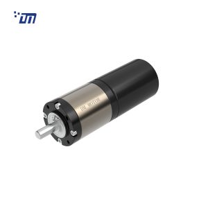
Add the gearbox: a small planetary stage at 0.85–0.9 efficiency or a multi-stage stack at 0.7–0.8 means the motor must be sized on output-shaft requirement divided by drivetrain efficiency, not on the datasheet stall torque alone. If your controller allows only 2 A continuous on a 24 V rail, that constraint, not torque, often decides the motor. This is the same working-point logic we explain in our guide to reading a motor datasheet: stall torque is a limit, never a sizing number.
Speed and Ratio: Respect the Vend-Cycle Clock
Vend experience research and machine-build practice converge on one number: the customer should see product drop within 2–4 seconds of pressing the button. That translates to one spiral revolution in 2–3 s, i.e. 20–30 rpm at the coil for the common 2–3 s machines, down to 5–10 rpm for gentle-delivery machines that handle fragile items.
This is where ratio selection becomes a genuine trade-off, not a lookup:
- Too little reduction (say 20:1 on a 3,000 rpm motor → 150 rpm) means the coil spins fast but torque collapses; a full lane stalls on breakaway and the controller sees overcurrent. Jams that look like a mechanical problem are frequently an under-geared drive.
- Too much reduction (200:1 → 15 rpm but weak margin) delivers torque but drags the vend cycle past 6 s, and users press the button again — doubling effective stall exposure.
For a 24 V machine with a 3,000–6,000 rpm motor, ratios between 60:1 and 150:1 cover most spiral lanes; planetary stages give the compactness vending cabinets demand, and the stage-by-stage efficiency math is the same as our planetary gear motor calculation guide. One practical note from our production floor: when a machine family serves both heavy cans and light snacks, we would rather supply two ratio variants of the same frame than stretch one ratio across both — the inventory cost is smaller than the service cost of a marginal design.
Duty Cycle: S3, Not S1
Vending drives do not run continuously, but they are not “light duty” either. The correct frame is intermittent periodic duty (duty type S3 under IEC 60034-1): short, repeated starts from standstill with a thermal cycle each time. Inrush on a brushed 24 V drive at breakaway can reach 3–7 A even when running current is 0.5–1 A, and winding temperature during a stall climbs fast — the 7 A stall and 3.4 Ω winding resistance we measured on a 58 mm worm drive platform corresponds to ~167 W dissipated in the windings within seconds of a jam.
Sizing guidance:
- Specify the rated point at the actual vend load, then check the motor survives a 3 s full-voltage stall per IEC 60034-1 duty definitions without exceeding its insulation class temperature limit.
- Current-sense stall detection at 0.5–2 s belongs in the controller spec, written into the drive’s acceptance test — not discovered in the field.
- For machines in 24-hour locations (transit hubs, hospitals), require the gear motor platform to also pass a no-load endurance test at elevated cycle counts, because door and flap drives accumulate hundreds of thousands of short cycles over machine life.
We cover the full S1/S2/S3 framework, including the torque-equal-RMS shortcut, in Motor Duty Cycles: S1, S2 and S3 Explained for Gear Motors.
Back-Driving and Holding: Where Worm Drives Earn Their Place
Elevator-style delivery lifts the product 300–800 mm vertically. If the gearbox can be back-driven when power is removed, the carrier drifts down under load, cables slack, and the next vend starts from an unknown position. Two solutions exist:
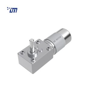
- Worm gearing with a lead angle below the friction angle is self-locking: the load cannot back-drive the motor. A worm stage costs efficiency (typically 50–70% for small, single-reduction units) but buys a mechanical hold with zero control effort. We explain the geometry and the real-world caveats — including why self-locking degrades as speed and temperature rise — in Worm Gear Motor Self-Locking: Lead Angle, Friction Angle and Back-Driving.
- Braked BLDC or a stepper with holding current avoids the worm’s efficiency penalty but adds a brake component and controller complexity, and holding current burns power continuously in a machine that is energized 24/7.
Our position: for elevator delivery in mainstream vending machines, a self-locking worm stage on the lift axis remains the lower-total-cost answer, precisely because holding is a safety-adjacent function, not an efficiency metric. Use brushless planetary where efficiency and low noise matter more than holding — the spiral and spring lanes.
Noise, Cold Cabinets and IP: The Environment Audit
Vending places drives in an acoustically unforgiving box: a sheet-metal cabinet amplifies gear mesh tones, and machines stand in offices, hotel corridors and hospital wards.
- Target ≤ 50 dB(A) at 1 m for indoor machines, measured with the delivery mechanism running under load. Gearbox whine scales with gear quality: plastic (POM) first stages are quieter and self-lubricating but cap torque; steel final stages carry the load. A mixed plastic-steel train is the usual sweet spot.
- Cold beverage cabinets run at 2–8 °C; outdoor machines see worse. Grease viscosity dominates breakaway torque at low temperature — a drive sized on room-temperature breakaway will stall at 0 °C on the same lane. Specify low-temperature grease and validate breakaway at the cabinet minimum, not the lab bench.
- IP rating: internal drives in a sealed cabinet are fine at IP40–IP54; anything near the delivery chute or on outdoor machines should be IP54 minimum, with the understanding that IP65 comes at a cost in shaft-seal friction and noise. IEC 60529 defines what each digit actually guarantees — the second digit (water) is the one outdoor machine buyers routinely over- or under-specify.
Four Failure Patterns We See in Returned Vending Drives
Field returns tell you where specifications were incomplete. Four patterns account for most of what comes back to our floor:
- Under-geared spiral drives. The machine passed bench tests with light snacks, then failed at sites stocking multipack snacks and glass bottles. The gearbox was never the weak part — the assumption about payload was. Sizing must use the heaviest product the operator can load, not the product the design brief mentioned.
- Stall without a detection window. The drive survives the first jam; the controller retries five times in a row and the fifth stall finishes the windings. Retries need a cooling gap of several seconds, and the current threshold needs hysteresis, otherwise the drive oscillates in and out of stall.
- Cold-cabinet breakaway. Grease stiffens, breakaway torque rises 30–60% at 2 °C versus 25 °C, and the drive that starts fine in the Shenzhen factory will not start a lane in an outdoor machine in January. This is a lubrication and margin problem, not a motor problem — pick grease for the cabinet minimum temperature.
- Vibration-loosened mounts. Spiral drives see a torque pulse every vend. Mounting screws without washers or thread locker walk out over months of service, then the gearbox misaligns with the coil coupling and wears the shaft seal. It costs nothing to specify spring washers and inspect points.
Each of these is fixable on paper before it becomes a service line item, which is why we ask for the load and environment data in the RFQ checklist below rather than quoting from a motor number alone.
Brushed vs Brushless for High-Traffic Machines
A pragmatic split we recommend to machine builders:
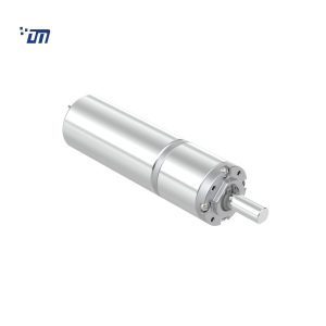
- Brushed DC, 12 V or 24 V: the default for flap, spring and light snack lanes. Lowest cost, trivial drive electronics, and with vend counts under a few hundred per day, brush life is rarely the limiting factor.
- Brushless (BLDC) with Hall feedback: for heavy lanes, elevator drives and premium machines where energy labels, telematics and quiet operation matter. Electronic commutation removes the brush-wear service item and, with current feedback, gives you fast, accurate stall detection — the single most valuable diagnostic on a spiral lane.
The deciding question is not “which is better” but where the drive sits in the failure-cost ranking. A failed flap motor is a nuisance; a failed elevator drive in a machine with no mechanical hold can dump product and jam the delivery door.
RFQ Checklist: What to Send the Motor Manufacturer
If this is your first time specifying a drive for a dispense mechanism, our overview of how to choose the right motor covers the general framework; the ten items below add the vending-specific data that turns a catalog guess into a quotable, testable proposal:
- Product mass range per lane (min/max, in kg)
- Delivery mechanism type and geometry (coil diameter, pitch, lane length)
- Vend cycle time target and daily vend count
- Supply rail (12 V / 24 V) and the controller’s current limit
- Stall detection window (ms) and allowed stall current
- Noise limit in dB(A) at 1 m, and where the machine will be placed
- Cabinet temperature range (including cold cabinet minimum)
- Required holding behavior on the lift axis (self-lock vs brake)
- Life target: vend cycles for lanes, cycles for door/flap drives
- Shaft, mounting and connector drawings (or ask for our standard options)
FAQ
How much torque does a vending machine spiral motor need?
For typical snack-and-drink machines, working torque at the spiral is 0.4–0.6 N·m with breakaway up to 1.5–2× that value after gearbox losses. Compute it from your heaviest product, the coil geometry and a 3–4× stacking factor rather than copying another machine’s motor.
Why does our vending motor burn out on jams?
A wedged package is a full-voltage stall: winding dissipation jumps to stall power (hundreds of watts in small drives) within seconds. If the controller’s stall-detection window is too long — or missing — the winding insulation exceeds its temperature class. Fix the detection window first; then verify the motor’s stall survival time.
Is a worm gear necessary in a vending machine?
Only where the load must not back-drive the motor — elevator delivery is the classic case. Spiral and spring lanes do not need self-locking and are better served by planetary stages, which are more compact and efficient.
Can one motor ratio serve both snack and drink lanes?
Sometimes, but it is rarely optimal. Drinks need roughly 3–5× the torque of snack lanes on the same mechanism style. Two ratio variants of the same frame size usually cost less in total than one stretched design’s service failures.
What noise level should we specify?
≤ 50 dB(A) at 1 m measured under load is a reasonable indoor-machine target. Insist on load testing: no-load noise can be 10 dB(A) lower and tells you almost nothing about gear mesh behavior with real product in the lane.