
Worm Gear Motor Self-Locking: Lead Angle, Friction Angle and Back-Driving
A 24 V worm gear motor holding a 15 kg roller shutter at the top of its travel can work for months and then, on a warm afternoon, let the shutter creep down 40 mm in eight hours. Nothing has failed. The motor still runs, the gearbox still turns, the load still holds — mostly. What changes is the temperature inside the housing, and with it the friction coefficient at the worm mesh. It is one of the most common field patterns in small worm drives, and it is entirely predictable from the geometry.
That pattern is the reason this article exists. “Self-locking” is printed on a lot of worm gear motor datasheets as if it were a binary property, like the shaft diameter. It is not. It is the outcome of an inequality between two angles, and both of those angles move with speed, temperature, lubricant and wear. If you are specifying a DC worm gear motor to hold a load without a brake, you need to know which side of that inequality your design sits on — and how much margin you have before it crosses over.
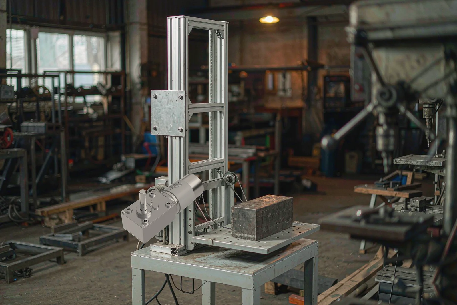
A 24 V worm gear motor holding a load on a lift column: what keeps it there is friction at the mesh, not a brake.
The Self-Locking Condition Is an Inequality, Not a Feature
A worm drive is self-locking when the worm wheel cannot drive the worm. Put a torque on the output shaft with the motor de-energised and nothing rotates. The condition for that, from classical machine-element theory, is short:
λ ≤ ρ′
λ is the lead angle of the worm — the angle between the thread helix and a plane perpendicular to the worm axis, measured on the pitch cylinder. ρ′ is the effective friction angle at the mesh, where tan ρ′ = μ′ and μ′ is the effective coefficient of friction. In the simplest form μ′ is just μ; a cos αn correction for a 20° normal pressure angle shifts the angle by roughly 6%, which is small next to the spread in μ itself.
Read that inequality carefully, because everything else in this article follows from it. It does not say “high ratio locks.” It says the lead angle has to be at or below the friction angle. Both sides are variables.
What the friction angle really is
Most design tables quote a single friction coefficient for a steel worm running against a bronze wheel. Field data does not support a single number. Standard worm gear design references tabulate μ against sliding speed, and the spread is not small.
For a case-hardened, ground and polished steel worm running with a phosphor bronze wheel in mineral oil of 60–130 cSt at 60 °C, the BS 721 and AGMA worm gear design data gives μ from about 0.145 at standstill down to 0.016 at 30 m/s sliding speed. Convert those into friction angles and the self-locking boundary moves by a factor of five.
| Sliding speed at the mesh | Friction coefficient μ | Friction angle ρ′ = arctan μ | Self-locks if lead angle λ ≤ |
|---|---|---|---|
| 0 (standstill, first breakaway) | 0.145 | 8.2° | 8.2° |
| 0.05 m/s | 0.09 | 5.1° | 5.1° |
| 0.5 m/s | 0.055 | 3.1° | 3.1° |
| 1 m/s | 0.044 | 2.5° | 2.5° |
| 5 m/s | 0.023 | 1.3° | 1.3° |
| 10 m/s | 0.018 | 1.0° | 1.0° |
The table is derived from friction data for that material pair in the worm gear design literature, and it explains the shutter: at standstill the mesh had μ ≈ 0.145 and would hold a lead angle of up to 8°. Once the oil in the sealed housing reached 75–80 °C, viscosity dropped, the film thinned, μ fell toward 0.05–0.07, and the boundary moved down to roughly 3–4°. A drive designed at 5° was suddenly on the wrong side of the line.
Design rule: size the self-locking margin against the friction angle at the highest expected sump temperature and the lowest expected sliding speed, not against the room-temperature bench number. A 2° margin is thin. A 3–4° margin is work.
Why the Lead Angle Falls as the Ratio Rises
Lead angle comes straight out of the worm geometry:
tan λ = (z₁ × m) / d₁
z₁ is the number of starts (threads) on the worm, m is the axial module, d₁ is the pitch diameter of the worm. The same relationship is often written as tan λ = z₁ / q, where q = d₁ / m is the diametral quotient.
Two consequences follow, and they pull in opposite directions for anyone who wants both a big reduction and a locked output.
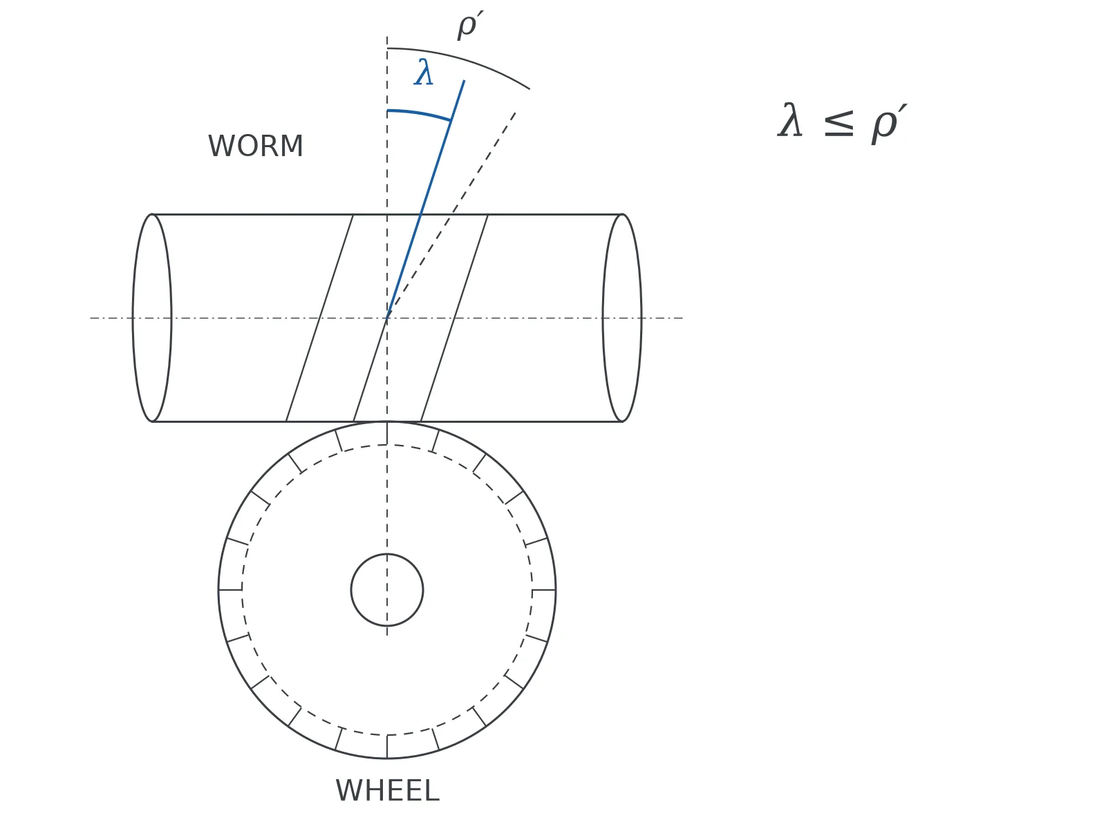
Lead angle γ is measured on the pitch cylinder between the thread helix and a plane normal to the axis. Self-locking needs γ at or below the friction angle ρ′.
A worked comparison: one start versus two
Take a 32 mm worm gearbox with a 0.8 mm module and a 9 mm worm pitch diameter.
- Single start (z₁ = 1): tan λ = 0.8 / 9 = 0.0889, so λ = 5.1°.
- Two starts (z₁ = 2): tan λ = 1.6 / 9 = 0.178, so λ = 10.1°.
At a running friction angle near 3°, the single-start unit sits 2° above the line — it holds at standstill and may creep when warm or vibrating. The two-start unit at 10.1° is nowhere near self-locking; it will back-drive under a light push. Yet both are “worm gearboxes with the same housing,” and both appear on supplier websites with the same photograph.
Ratio is not the design variable here. Starts and pitch diameter are. A single-start 40:1 unit with q = 10 gives λ = 5.7°, which locks in cool conditions. A two-start 20:1 unit on the same housing gives λ ≈ 11.3°, which does not. If holding is the requirement, specify the number of starts explicitly and ask for the lead angle printed on the drawing.
| Ratio band (single start) | Typical lead angle | Forward efficiency | Back-driving risk |
|---|---|---|---|
| 5:1 – 10:1 | 12° – 18° | 75% – 88% | Back-drives freely; needs a brake |
| 15:1 – 25:1 | 7° – 10° | 65% – 80% | Back-drives under load |
| 30:1 – 40:1 | 4° – 6° | 50% – 65% | Marginal; verify at operating temperature |
| 50:1 – 100:1 | 2° – 3.5° | 35% – 50% | Holds in clean, cool, static conditions |
| 120:1 and above | under 2° | 25% – 40% | Holds with margin; heat becomes the limit |
The ratio-to-angle mapping in that table assumes the diametral quotient grows with ratio, which is how most catalogue designs are built. It is a trend, not a law: two gearboxes at the same 40:1 ratio can differ by several degrees of lead angle depending on worm diameter and module. Ask for the drawing.
Efficiency Sits on the Other Side of the Same Equation
The same geometry that gives you holding takes away efficiency. Forward efficiency for a worm stage is approximately:
η = tan λ / tan (λ + ρ′)
Set λ = 5° and ρ′ = 5° and you get η ≈ 0.49. That is the whole trade in one line: a drive that is reliably self-locking cannot also be efficient, because both outcomes are produced by the same sliding contact. The rule of thumb that circulates in drive engineering — a worm drive self-locks when forward efficiency drops to about 50% — is not folklore, it falls out of the reverse-efficiency approximation η′ ≈ 2 − 1/η.
The practical cost: at 40% efficiency, a 30 W output needs roughly 75 W of input, and the difference leaves as heat in the gearbox. That input-output gap is exactly what the loss-determination methods in IEC 60034-2-1 are built to separate into its components. Our own experience across small worm gearboxes is that the units customers call “overheating” are almost always high-ratio units doing continuous duty that the application never budgeted thermal headroom for. If the duty cycle is S1 and the ratio is above 60:1, check the thermal limit before you check anything else.
This is also where the honest trade-off sits. For most 12 V and 24 V applications that need holding, a 50:1 to 80:1 single-start worm gearbox is the right answer, and the efficiency you give up is the price of not fitting a brake. If the application needs both 80% efficiency and a locked output, the requirement is contradictory: pick a planetary gear motor and add a brake, or accept the worm’s losses.
Four Things That Quietly Cancel Self-Locking in Service
A design that passes the inequality on paper can still creep in the field. These are the mechanisms we see, in rough order of how often they cause trouble.
Heat
Sump temperature of 80–90 °C thins the oil film and drops the effective friction coefficient. Continuous-duty worm gearboxes in sealed metal housings routinely run 40–55 °C above ambient, so a 35 °C summer day puts the grease at 75–90 °C. Verify the lock condition at that temperature, not at 20 °C on a bench.
Vibration and shock
Static friction is what holds the load, and every shock cycle momentarily breaks static contact. A conveyor that indexes, a door that slams, a vehicle-mounted actuator on a rough road — each event advances the output by a small angle. Over hours, small angles add up to a visible drop. Standard worm gear references are explicit about this: it is safer to design against the dynamic friction coefficient than the static one precisely because vibration brings the lower value into play.
Lubricant and wear
Extreme-pressure additives and low-viscosity synthetic oils do exactly what they are sold to do — reduce friction. That is the same thing as reducing your holding margin. Running-in polishes the flanks and lowers μ further over the first few hundred hours. A gearbox that held during the factory test may not hold after 500 hours.
Load direction and geometry
A worm drive resists back-driving most effectively when the load pushes along the line the teeth were cut for. Side loads, off-centre mounting and a flexible output coupling turn part of the load into a tipping moment that the mesh was never designed to resist. Rigid mounting and a properly supported output shaft are part of the holding function, not just installation hygiene.
How to Test Back-Driving on the Bench
Catalogue claims are cheap; a breakaway test takes twenty minutes. Do this before you commit a production run.
- Run the gearbox to operating temperature first. Load it at rated torque for 30–45 minutes, or soak it in an oven at the expected ambient plus 40 °C. A cold test tells you nothing about the condition that matters.
- Disconnect the motor and leave the leads open. Do not short them. Shorting the brushes creates dynamic braking that will make a non-locking gearbox look locked, and you will ship a design that fails in the field.
- Apply torque gradually to the output shaft with a torque wrench or a lever and a spring scale. Record the torque at which rotation starts. Take five readings; the first is usually highest because of stiction, so report the minimum and note the spread.
- Compare against the load torque with a factor. Require a breakaway torque of at least 1.5× the maximum static load torque, and preferably 2× where a person or a product sits under the load.
- Run a creep test. Leave the rated load applied for 30 minutes with the motor de-energised and measure output rotation with a dial indicator or an encoder. Zero rotation over 30 minutes at operating temperature is a far better acceptance criterion than a catalogue sentence.
For a small gearbox (a 40 mm class unit delivering 80 kgf·cm, roughly 7.8 N·m) a breakaway torque above 12 N·m at 70 °C is a reasonable pass line for a holding duty. Below that, add a brake.
When Back-Driving Is the Feature You Want
Not every application wants a locked output, and treating self-locking as a universal virtue is a common specification error. Three cases where you should deliberately choose a drive that back-drives:
- Manual override. Window openers, gate operators and valve actuators that must be cranked by hand during a power failure. A self-locking worm drive fights the person turning the handle.
- Energy recovery and controlled run-down. Fan rotors, centrifuges and flywheel loads that must coast to a stop rather than stop dead.
- Position compliance. Anything that has to yield when a person or an obstacle pushes against it — a locking drive becomes a safety hazard rather than a feature.
If you are in one of these cases, specify a two-start worm or move to a spur or planetary stage, and handle holding with an external brake.
What to Put in the RFQ
Vague requirements get vague quotes, and “self-locking” is the vaguest term in this corner of the catalogue. Six items to ask for in writing:
- Lead angle on the drawing, in degrees — not a yes/no self-locking checkbox.
- Number of starts on the worm, and the ratio that follows from it.
- Material pair and surface treatment of the worm and wheel. A hardened, ground steel worm against a centrifugally cast bronze wheel behaves differently from an unhardened pair.
- Lubricant specification — grade, base oil, and whether it carries EP additives. This changes μ, and therefore changes the holding margin.
- Breakaway torque at stated temperature, measured on a sample, with the test temperature recorded.
- Duty cycle and expected sump temperature, so the supplier can check the thermal limit alongside the holding requirement.
That list is also the fastest way to find out whether a supplier understands worm drives. A supplier who answers with a lead angle and a temperature has done the calculation. A supplier who answers “yes, self-locking” has read the same catalogue line you did.
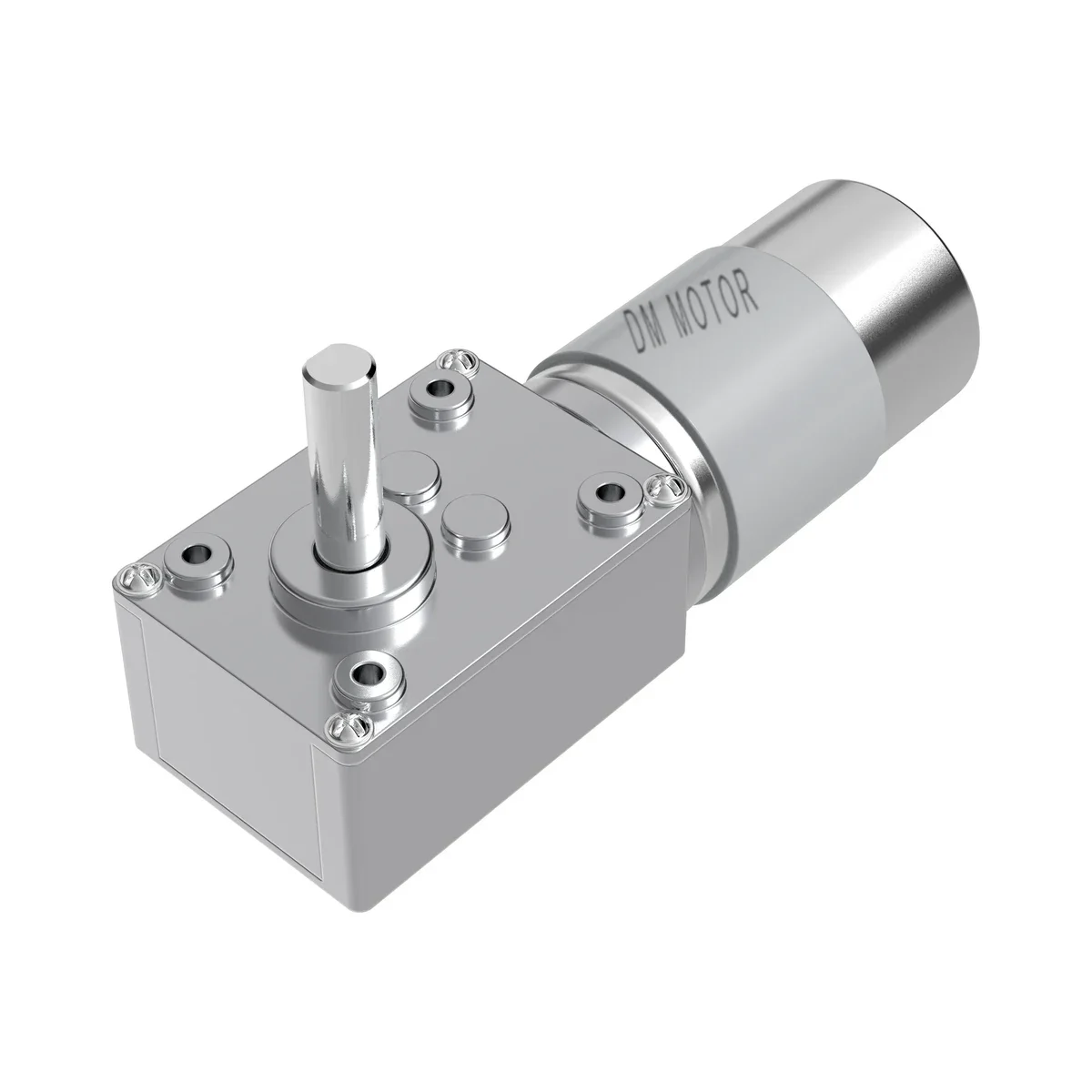
DM-58WM555: 40.1 mm gearbox, 12–24 VDC, 2–122 rpm, up to 80 kgf·cm.
Frequently Asked Questions
Is a worm gear motor always self-locking?
No. Self-locking depends on the lead angle being at or below the effective friction angle. Single-start worms at ratios above roughly 40:1 usually qualify in cool, clean, static conditions. Two-start and four-start worms at 10:1–25:1 almost never do. Between those bands, the answer depends on lubricant, temperature and vibration, and it has to be verified rather than assumed.
Can a self-locking worm gear motor be back-driven by vibration?
Yes, and it is the most common field failure of a design that passed on paper. Static friction holds the load; every shock or vibration cycle breaks that contact and lets the output advance a fraction of a degree. Over hours the load visibly drops. Where the load is a safety issue, fit a brake and treat the worm mesh as secondary protection.
Does a higher gear ratio always mean better holding?
It improves the odds, because lead angle falls as ratio rises for a single-start worm. It does not lock the output by itself. A 60:1 two-start unit can have a larger lead angle than a 40:1 single-start unit. Ratio is a proxy; lead angle is the actual variable.
Do I still need a brake on a self-locking gearbox?
For any suspended load — a hoist, a lift column, a shutter, a gate that closes under gravity — yes. Self-locking is friction-based, and friction is the one thing in the assembly that changes with temperature, wear and lubrication. A brake is a positive mechanical action. Use the worm mesh to reduce brake wear and to hold position after the brake engages, not as the only barrier.
How can I tell from a datasheet whether a unit will hold?
Ask for the lead angle and the ratio. If the lead angle is 5° or lower and the unit is single-start, it will hold in normal indoor conditions with a reasonable margin. Below 3.5° the margin is comfortable up to about 70 °C. Then confirm with a breakaway test at temperature, because the datasheet’s rated torque and speed tell you nothing about holding.
Getting the Holding Margin Right Before You Order
The numbers in this article come from standard worm gear design practice — the friction-angle inequality is in every machine-element textbook, and the efficiency expression is the one used in BS 721 and AGMA worm gear design. What is less standard is applying them at the temperature the gearbox actually reaches.
Our worm gear motor range covers 12 mm to 50 mm gearbox widths, 3–24 VDC, output speeds from 2 rpm to 250 rpm and torque up to 80 kgf·cm in the 40 mm class — ratios and lead angles that put most units in the holding band when built single-start. The full range sits inside our complete guide to DC gear motors alongside the spur, planetary and square families.
| Model | Gearbox width | Voltage | Speed range | Torque range |
|---|---|---|---|---|
| DM-1220WMN20 | 12 × 20 mm | 3–12 VDC | 2–250 rpm | 0.1–5 kgf·cm |
| DM-46WM370 | 32 mm | 6–24 VDC | 2–250 rpm | 1–27 kgf·cm |
| DM-58WM555 | 40.1 mm | 12–24 VDC | 2–122 rpm | 1–80 kgf·cm |
| DM-75WM555 | 50 mm | 12–24 VDC | 2–50 rpm | 0.5–70 kgf·cm |
If your application holds a load with the motor off, send the load torque, the duty cycle and the maximum ambient temperature. We will come back with the lead angle and the measured breakaway torque at temperature, which is the only pair of numbers that answers the question. Start with the full worm gear motor overview if you are still narrowing the gearbox type, or read the planetary versus worm comparison if efficiency matters more than holding. Every unit we ship is checked against our quality control process before it leaves, and our engineers will review your holding requirement against the drawing rather than the catalogue page.