
How to Extend the Lifespan of Your Brushless DC Motor
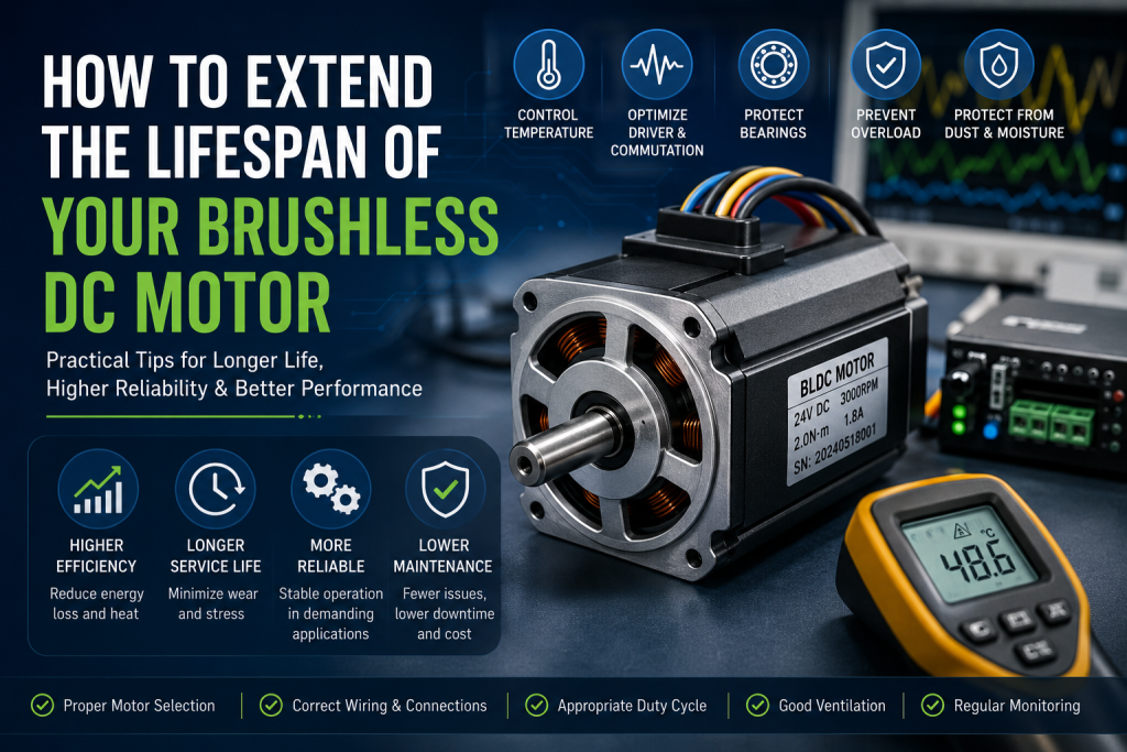
Table of Contents
- What Determines BLDC Motor Lifespan?
- Avoid Continuous Overload and Excessive Current
- Control Motor Temperature
- Select the Correct BLDC Motor and Operating Point
- Optimize the Motor Driver and Commutation
- Use the Correct PWM and Speed-Control Strategy
- Protect Bearings and Mechanical Components
- Avoid Excessive Starts, Stops, and Acceleration
- Consider Duty Cycle and Operating Environment
- Protect the Motor from Dust and Moisture
- Monitor Motor Performance
- BLDC Motor Maintenance Checklist
- Frequently Asked Questions
- Conclusion
What Determines BLDC Motor Lifespan?
Unlike brushed DC motors, BLDC motors do not use mechanical brushes and a commutator for electronic commutation. This eliminates brush wear and reduces one major source of maintenance.
However, other components still experience electrical, thermal, and mechanical stress.
The main factors affecting BLDC motor lifespan include:
- Winding temperature
- Operating current
- Load torque
- Operating speed
- Bearing condition
- Rotor balance
- Motor driver performance
- Commutation accuracy
- PWM frequency and control method
- Duty cycle
- Ambient temperature
- Dust and moisture
- Mechanical vibration
- Gearbox loading in BLDC gear motors
For most applications, temperature and mechanical stress are two of the most important factors to control.
1. Avoid Continuous Overload and Excessive Current
One of the most effective ways to extend BLDC motor life is to avoid operating continuously near the motor’s maximum torque or current.
When motor torque increases, phase current generally increases. Higher current increases copper loss in the windings:
P₍copper₎ = I²R
Because copper loss increases with the square of current, a relatively small increase in current can produce a significant increase in heat generation.
For example, increasing current from 2 A to 3 A results in:
(3 / 2)² = 2.25
Therefore, the theoretical copper loss becomes approximately 2.25 times higher, assuming winding resistance remains constant.
Practical Recommendation
During application testing, measure:
- No-load current
- Normal operating current
- Peak current
- Startup current
- Operating temperature
If the motor consistently operates close to its maximum continuous current, consider:
- Reducing the mechanical load
- Increasing the gear ratio
- Selecting a higher-torque motor
- Increasing motor size
- Improving cooling
- Reducing acceleration requirements
For a BLDC gear motor, evaluate the motor and gearbox together rather than evaluating motor torque alone.
2. Control Motor Temperature
Thermal management is critical to BLDC motor reliability.
Excessive temperature can accelerate insulation aging, degrade permanent magnets, affect bearings and lubricants, and reduce the long-term reliability of electronic components.
A motor’s temperature is influenced by:
Current + Speed + Load + Duty Cycle + Ambient Temperature + Cooling Conditions
How to Reduce BLDC Motor Temperature
- Avoid continuous operation near maximum torque.
- Improve airflow around the motor.
- Keep ventilation openings clear.
- Use an appropriate motor housing.
- Improve heat conduction through the mounting structure.
- Reduce unnecessary mechanical friction.
- Use thermal monitoring when required.
For compact BLDC motors installed inside enclosed equipment, thermal validation should be performed in the actual enclosure, not only on an open laboratory test bench.
A motor that operates safely in open air may reach a much higher temperature after installation inside a small plastic housing.
To learn more about the thermal principles of motors, please refer to <DC Motor Overheating Causes & Prevention>
3. Select the Correct BLDC Motor and Operating Point
Correct motor selection is one of the best ways to extend service life.
Do not select a BLDC motor based only on its maximum speed or peak torque.
Engineers should consider:
- Rated voltage
- Operating voltage
- Continuous torque
- Peak torque
- Rated speed
- Required output speed
- Phase current
- Duty cycle
- Ambient temperature
- Installation space
- Cooling conditions
- Required service life
Ideally, the normal operating point should provide sufficient margin below the motor’s maximum continuous capability.
Example
If an application requires 0.8 N·m continuously, selecting a motor whose continuous torque capability is only 0.8 N·m leaves little margin for:
- Increased ambient temperature
- Mechanical friction
- Manufacturing tolerance
- Voltage variation
- Aging
- Unexpected load changes
A motor with additional continuous torque capacity can provide greater thermal and performance margin.
For more information about DC motor selection, please refer to 《Micro DC Motor Sizing Guide: Selecting the Right Voltage, RPM, and Torque for Compact Devices》
4. Optimize the Motor Driver and Commutation
A BLDC motor depends on its electronic driver for commutation.
Unlike a brushed DC motor, where the mechanical commutator automatically switches winding current, a BLDC system uses electronic switching to control the motor phases.
The driver must correctly manage:
- Phase switching
- Rotor position
- Commutation timing
- Current limits
- PWM control
- Acceleration
- Braking
- Fault protection
Incorrect commutation timing can increase torque ripple, vibration, current consumption, and motor temperature.
Hall-Sensor BLDC Motors
For Hall-sensor BLDC motors, the controller uses Hall signals to determine rotor position.
Incorrect Hall wiring, incorrect phase sequence, or inappropriate commutation logic can cause:
- Poor starting performance
- Excessive current
- Abnormal vibration
- Reduced efficiency
- Motor heating
Therefore, during system integration, verify the relationship between:
Hall A / Hall B / Hall C → Phase U / V / W → Controller commutation logic
This is especially important for customized BLDC motor systems.
Introduction to Hall Sensors <Why Some Motors Use Encoders>
5. Use the Correct PWM and Speed-Control Strategy
PWM is commonly used to control BLDC motor speed and torque.
However, the controller should be properly matched to the motor and driver.
Important parameters include:
- PWM frequency
- Duty cycle
- Current limit
- Acceleration ramp
- Deceleration ramp
- Switching strategy
A poorly configured controller may create unnecessary electrical and mechanical stress.
For example, repeatedly commanding rapid acceleration from zero to maximum speed can generate high peak current and mechanical shock.
A controlled acceleration ramp can reduce:
- Peak current
- Mechanical shock
- Gearbox stress
- Bearing load
- System vibration
For applications requiring frequent speed changes, the control profile should therefore be considered as part of BLDC motor lifespan optimization.
6. Protect Bearings and Mechanical Components
Although BLDC motors eliminate brush and commutator wear, bearings remain a major mechanical wear component.
Bearing life can be affected by:
- Radial load
- Axial load
- Shaft misalignment
- Excessive vibration
- High temperature
- Contamination
- Excessive speed
Avoid applying loads to the motor shaft that exceed the manufacturer’s specifications.
For applications using belts, pulleys, gears, or wheels, engineers should carefully evaluate the radial and axial forces applied to the shaft.
Alignment Matters
Poor alignment can increase bearing load and vibration.
Check:
- Shaft concentricity
- Coupling alignment
- Mounting surface accuracy
- Radial load
- Axial load
For high-speed BLDC motors, even relatively small mechanical imbalance can produce significant vibration.
7. Avoid Excessive Starts, Stops, and Acceleration
Frequent starts and stops can significantly increase thermal and mechanical stress.
During startup, a BLDC motor may require substantially higher current than during steady-state operation, particularly when accelerating a high-inertia load.
Applications with frequent cycling should therefore consider:
- Rotor inertia
- Load inertia
- Acceleration time
- Peak current
- Number of starts per hour
- Braking method
- Duty cycle
Instead of asking only:
Can the motor reach the required RPM?
Engineers should also ask:
How many times per hour must the motor accelerate, decelerate, stop, and reverse?
This distinction is important when estimating the real operating life of a BLDC motor or BLDC gear motor.
8. Consider Duty Cycle and Operating Environment
A motor rated for intermittent operation should not automatically be treated as a continuous-duty motor.
For example:
- 10 seconds ON / 50 seconds OFF
- 30 seconds ON / 30 seconds OFF
- 5 minutes ON / 5 minutes OFF
- Continuous operation
produce different thermal conditions even when the peak torque is identical.
The actual duty cycle should be included during motor selection and thermal testing.
Ambient Temperature
A motor operating at 25°C ambient and a motor operating at 50°C ambient do not have the same thermal margin.
Higher ambient temperature reduces the temperature difference between the motor housing and surrounding air, making heat dissipation more difficult.
For outdoor equipment, automotive applications, and enclosed industrial equipment, the maximum ambient temperature should be included in the design specification.
9. Protect the Motor from Dust and Moisture
Environmental contamination can reduce BLDC motor service life even when the electrical design is correct.
Dust can:
- Accumulate around cooling surfaces
- Increase bearing contamination
- Reduce heat dissipation
- Enter mechanical interfaces
Moisture can contribute to:
- Corrosion
- Bearing degradation
- Insulation problems
- Connector failure
For harsh environments, consider:
- Appropriate motor sealing
- Protective covers
- Suitable connectors
- Environmental-rated bearings
- Proper enclosure design
The required protection level should be determined by the actual application environment rather than selected only by motor size.
10. Monitor Motor Performance
Condition monitoring can identify problems before they cause permanent failure.
Useful parameters include:
Electrical
- Voltage
- Phase current
- DC bus current
- Hall sensor signals
- Driver fault status
Mechanical
- RPM
- Vibration
- Shaft load
- Bearing noise
Thermal
- Motor housing temperature
- Winding temperature where measurable
- Ambient temperature
- Temperature rise
A gradual increase in operating current at the same load and speed can be an early indication of:
- Bearing deterioration
- Gearbox friction
- Mechanical misalignment
- Increased load
- Electrical problems
This makes current and temperature trending useful tools for predictive maintenance of BLDC motors.
BLDC Motor Lifespan: Practical Diagnostic Table
| Symptom | Possible Cause | Recommended Check |
| High current + low RPM | Excessive load | Check load torque and mechanical resistance |
| High temperature + normal load | Poor cooling | Check airflow and enclosure |
| High current during startup | Excessive inertia/load | Check acceleration requirements |
| Vibration + abnormal noise | Bearing or alignment issue | Check shaft and bearings |
| High current + poor efficiency | Incorrect commutation | Check Hall/phase sequence and timing |
| Motor heats after gearbox assembly | Gearbox friction | Check gears, bearings, and lubrication |
| Increasing current over time | Mechanical wear | Compare current trend with baseline |
| Unstable speed | Driver/Hall/control issue | Check feedback and commutation |
BLDC Motor Maintenance Checklist
| Inspection Point | Recommended Action |
| Operating current | Compare actual current with design values |
| Motor temperature | Record temperature under actual load |
| Bearings | Check noise, vibration, and shaft play |
| Shaft alignment | Verify coupling and mounting accuracy |
| Hall sensors | Check signal sequence and stability |
| Motor driver | Verify current limit and commutation settings |
| Gearbox | Inspect friction, noise, and lubrication |
| Wiring/connectors | Check for loose or damaged connections |
| Cooling | Remove dust and verify airflow |
| Duty cycle | Confirm actual ON/OFF operating pattern |
Maintenance intervals should be determined according to motor construction, application conditions, operating hours, and manufacturer recommendations.
How to Extend the Lifespan of a BLDC Gear Motor
For a BLDC gear motor, the gearbox introduces additional factors that can affect service life.
The system should be evaluated based on:
Motor + Gearbox + Load + Controller + Thermal Environment
Important considerations include:
Gearbox Efficiency
Higher friction means more input torque is required from the motor, which can increase motor current and temperature.
Output Load
Avoid continuously operating the gearbox close to its maximum rated output torque.
Lubrication
Use the appropriate lubricant and operating temperature range specified for the gearbox.
Gearbox Alignment
Poor assembly or excessive external shaft loading can increase gear and bearing stress.
Thermal Interaction
The gearbox and motor are physically connected, so heat generated by one component can affect the thermal conditions of the other.
For compact robotic actuators and automation systems, thermal testing should therefore evaluate the complete BLDC gear motor assembly rather than the motor alone.
FAQ
How long does a BLDC motor typically last?
There is no universal service-life number for every BLDC motor.
Actual lifespan depends on bearing life, winding temperature, operating current, load, speed, duty cycle, environment, driver performance, and mechanical design.
A properly selected BLDC motor operating within its specified conditions can provide a long service life, but the application conditions determine the actual result.
Do BLDC motors require maintenance?
BLDC motors require less routine maintenance than brushed DC motors because they do not use mechanical brushes and commutators.
However, bearings, mechanical connections, cooling conditions, wiring, and the motor driver still require inspection depending on the application.
Does running a BLDC motor at high speed reduce its lifespan?
It can.
High speed can increase bearing stress, windage losses, vibration, and mechanical stress. The effect depends on motor construction and the specified operating speed range.
The motor should be operated within its rated speed and mechanical limits.
Does overheating shorten BLDC motor life?
Yes.
Repeated or continuous operation at excessive temperature can accelerate insulation aging, affect permanent magnets, degrade bearings and lubricants, and reduce overall reliability.
Thermal management is therefore one of the most important aspects of extending BLDC motor lifespan.
How can I make a BLDC motor last longer?
The most effective methods are:
- Select the correct motor for the actual load.
- Avoid continuous operation near maximum current.
- Control motor temperature.
- Use the correct motor driver and commutation settings.
- Avoid excessive acceleration and mechanical shock.
- Protect bearings from excessive radial and axial loads.
- Use the correct duty cycle.
- Protect the motor from dust and moisture.
- Monitor current, temperature, speed, and vibration.
How can I extend the life of a BLDC gear motor?
Select an appropriate gear ratio, keep continuous output torque within the gearbox rating, minimize mechanical friction, use the correct lubrication, avoid excessive shaft loads, and validate the complete motor-gearbox assembly under the actual duty cycle and thermal conditions.
Conclusion
Extending the lifespan of a Brushless DC motor is primarily a matter of controlling electrical, thermal, mechanical, and environmental stress.
The most important factors are not simply the motor’s rated power or maximum torque. Engineers should evaluate:
Current + Torque + Speed + Temperature + Duty Cycle + Bearing Load + Controller + Environment
A well-designed BLDC motor system should operate with sufficient performance margin rather than continuously approaching its maximum ratings.
For demanding applications such as robotics, AGVs, AMRs, automation equipment, medical devices, smart appliances, and compact actuators, testing the motor under the actual load, enclosure, ambient temperature, duty cycle, and control strategy is essential.
Proper motor sizing, thermal management, driver configuration, mechanical alignment, and condition monitoring can significantly improve reliability and help achieve a longer and more predictable BLDC motor service life.
For more motor knowledge, please refer to <https://szdmmotor.com/blog/>