
DC Motor Won’t Start? A Step-by-Step Diagnosis Guide for DC Gear Motors
A support ticket that says “the motor doesn’t run” hides at least six different failures behind four words. We build and repair small DC gear motors every day, and in our experience most no-start calls are won or lost in the first ten minutes — before anyone opens the gearbox. The fault is as often in the supply, a connector, or the load as it is in the motor itself.
This guide is the diagnostic sequence our own service engineers use on brushed and brushless DC gear motors from 12 mm to 58 mm. It moves from cheapest test to most invasive: supply first, no-load test second, electrical checks third, gearbox last. Follow it in order and you will either find the fault or know exactly what to send back to the manufacturer. If you need the reference numbers for your unit first, the worm gear motor datasheets on our DM-58WM555 product page show the exact no-load, maximum-efficiency and stall points this article refers to.
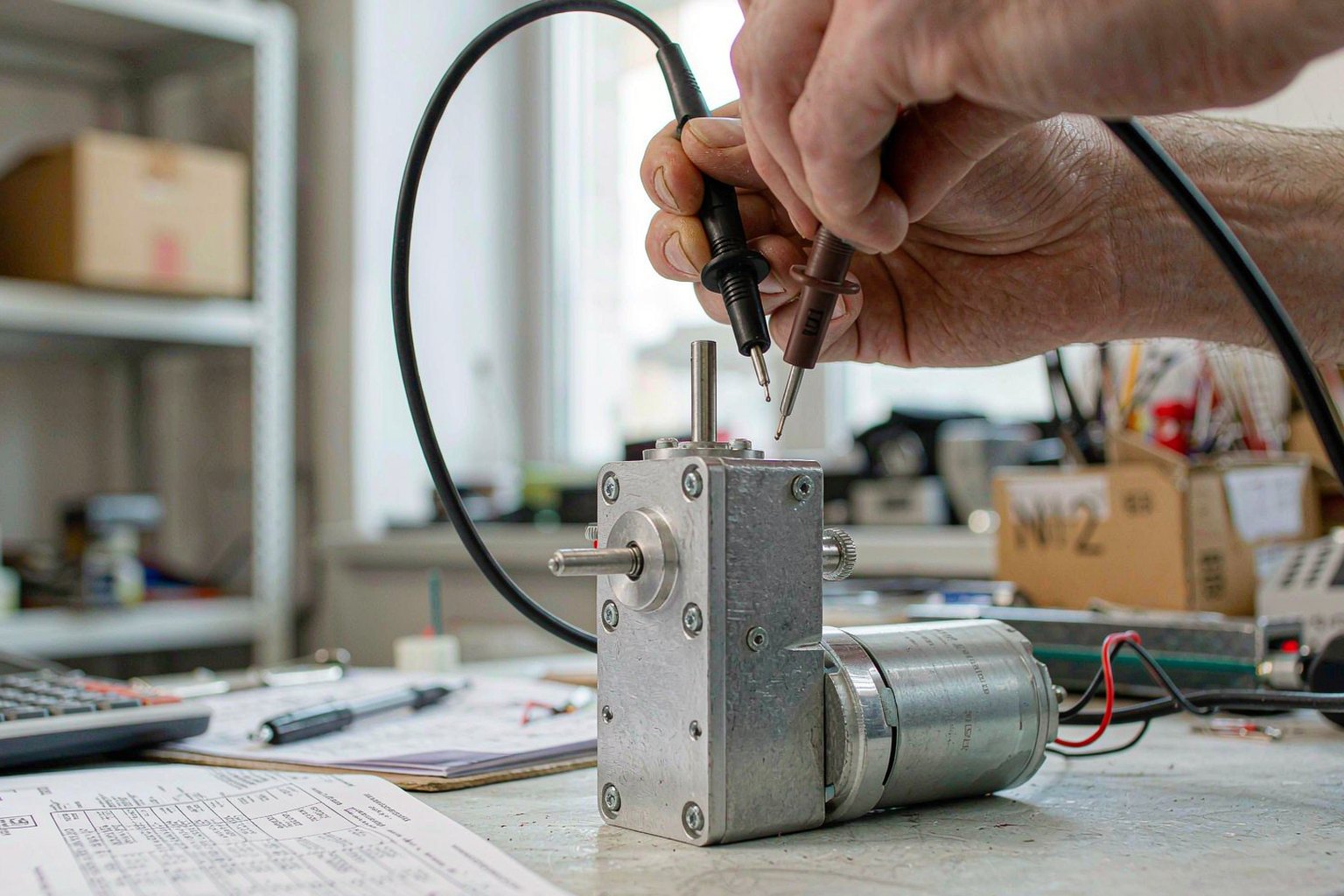
Bench diagnosis starts at the terminals: measure no-load current before assuming the gearbox is seized.
Start Here: The Ten-Minute, No-Tear-Down Sequence
Resist the urge to disassemble anything. A gearbox opened on the wrong hypothesis rarely goes back together with the same noise level. Work through this order instead:
- Measure supply voltage at the motor terminals, not at the power supply, while someone attempts a start.
- Check connectors, fuses and any inline switch for a dropped leg.
- Uncouple or lift the load and try a no-load run.
- If the shaft turns free, measure no-load current and compare it with the datasheet.
- Only then move to resistance and brush checks.
The table below compresses the whole sequence into the symptom patterns we see most often. Keep it near the bench.
| Symptom | Most likely cause | First measurement |
|---|---|---|
| Nothing at all, no hum, no heat | Supply, fuse, connector or dead controller | Voltage at motor terminals during a start attempt |
| Hum or vibration, shaft locked | Seized gearbox, jammed mechanism, or stalled rotor | Uncouple load, retry no-load |
| Runs free, stalls under load | Undersized motor, gearbox wear, or rising load friction | No-load current vs datasheet |
| Runs, then stops after minutes | Thermal protector tripping or duty-cycle overload | Housing temperature and repeat-time pattern |
| Starts only when shaft is nudged | Worn brushes or dead commutator segment | Terminal resistance while rotating shaft slowly |
| Controller resets when motor engages | Supply voltage sag under stall current | Supply voltage under load vs open-circuit |
Check the Supply Before You Blame the Motor
The single most common false diagnosis in our service inbox is a healthy motor replaced to fix a supply problem. A DC gear motor is specified at its rated voltage, and it will disappoint at anything below roughly 85–90% of that once load is applied.
Voltage Sag Under Load Is the Silent Killer
Open-circuit voltage lies. A battery or long cable run can read 24.0 V at rest and collapse below 19 V the moment the motor pulls starting current. Take our DM-58WM555 as an example of why this matters: in the 24 V configuration the datasheet lists stall current of 7 A or more. Divide rated voltage by stall current and you get the locked-rotor resistance the winding implies — 24 V ÷ 7 A ≈ 3.4 Ω. Any resistance between supply and motor — a tired battery, a corroded crimp, a 5 m lead that is too thin — drops voltage in proportion to its share of that 3.4 Ω. At 2 A of running current, just 0.5 Ω of extra path resistance steals 1 V; at the 7 A start, it steals 3.5 V, which is enough to pull a marginal controller into reset.
So measure at the motor terminals, with a meter, during the start attempt. If voltage collapses, the motor is innocent. Fix the supply path or raise the cable gauge before anything else.
Connectors, Fuses and Forgotten Switches
Before the meter, spend thirty seconds on the path. Re-seat connectors and look for a backed-out pin. Check fuses with a meter, not by eye — a glass fuse can look intact and still have a blown end cap. Thermal fuses buried inside the supply deserve the same suspicion. On machines that have been stored, oxidized switch contacts can pass a light load but arc and drop out under motor inrush; that fault pattern shows up as “it worked last month.”
The No-Load Test: Splitting the Problem in Half
One test separates mechanical from electrical faster than anything else: disconnect the load — lift the drive wheel off the floor, loosen the coupling, detach the cam — and apply rated voltage.
What No-Load Current Should Look Like
Compare your reading with the datasheet’s no-load column, and use the direction of the error to point at the fault:
- No-load current far below spec with the motor turning slowly or not at all: weak field or partial connection; on a permanent-magnet DC motor, suspect an open armature path.
- No-load current within spec and speed close to the rated no-load value: the motor and gearbox are almost certainly healthy; the fault is in the load or the supply under load.
- No-load current well above spec with rough running: bearing damage, bent shaft, or a gearbox with collapsed teeth — the motor is fighting its own friction.
On the DM-58WM555 in 24 V, the no-load current is specified at or below 0.21 A at 6,500 rpm. A unit drawing 0.2 A and spinning quietly is telling you the problem is downstream. A unit drawing 1 A at no load with a grinding noise has a mechanical fault no wiring fix will cure.
Runs Free but Stalls Under Load: The Gearbox or the Load
When the no-load test passes but the motor stalls the moment the load returns, you have three suspects left, and two of them are not the motor:
- The load has grown. Product jam, debris in a guide rail, a mechanism that has shifted and added binding friction. Rotate the load by hand — with the motor uncoupled and power off — and feel for tight spots through the full travel. A jam you can feel with fingers costs nothing to find.
- The gearbox is worn. Planetary gearboxes that have lost a planet carrier bearing still run free at no load but skip under torque; worm gearboxes with worn bronze wheels develop backlash and then jam. Worm units add a specific trap: self-locking. In the 3-stage ratios of a DM-58WM555 (54:1 and up), the lead angle is low enough that the output shaft cannot be back-driven — so a seized output looks identical to a dead motor from the outside. Our article on worm gear motor self-locking explains the geometry behind that behavior.
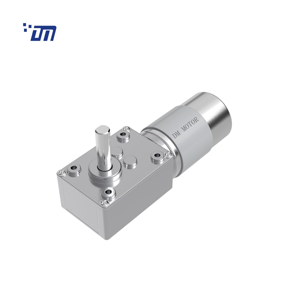
The DM-58WM555 spans 54:1 to 1327:1; its self-locking worm output can disguise a jammed mechanism as a dead motor.
- The motor is simply undersized for the real duty. This is a specification failure, not a component failure, and it is worth admitting early: if the application has grown heavier since the motor was chosen — heavier product, faster cycle, more friction from wear — the correct fix is a resized motor, not a repair. Our guide to reading a motor datasheet shows how to check the actual operating point against the stall and maximum-efficiency numbers instead of guessing.
Electrical Checks on a Brushed DC Motor
If the no-load test fails — no rotation, no current, or fuse-blowing current — the motor side needs a meter.
Terminal resistance. Measure resistance across the terminals while slowly rotating the shaft by hand. A healthy armature shows a stable reading that varies only slightly with shaft angle. A reading that jumps to open-circuit at regular intervals means a broken winding or a burned commutator segment; a near-short reading means damaged windings or shorted brushes bridging adjacent segments. Using the DM-58WM555 figures again: 24 V with a 7 A stall implies roughly 3.4 Ω locked-rotor resistance, so a cold reading in single-digit ohms is normal and a reading of a few tenths of an ohm is a short.
Brushes and commutator. Worn brushes are the classic intermittent no-start cause on brushed gear motors: the motor starts only when the shaft is nudged to a segment where the brush still contacts. Pull the brush caps and check that the brushes slide freely and still have material — most small motors give clear visual warning well before failure. Dark, pitted commutator segments with carbon dust packed in the grooves can be cleaned with a non-metallic abrasive; deep grooves mean the motor needs a bench decision, not a quick fix.
Brushless units behave differently. A BLDC gear motor that refuses to start is more often a controller, hall-sensor or wiring issue than a “motor” issue, because the motor itself is just windings. Confirm the hall signal sequence and the phase wiring before condemning the motor. Swapping phase wires on a three-phase BLDC during troubleshooting has brought back more “dead” motors than we can count.
Thermal Faults and the Motor That Stops After a Few Minutes
The pattern is distinctive: the motor runs fine cold, then stops after a consistent interval, then runs again after cooling. That is a thermal protector doing its job — or an insulation system approaching its limit while a protector is absent.
Three things drive it:
- Duty cycle exceeded. A motor rated for intermittent use is being run continuously, or the pause between cycles has quietly shrunk. Compare the real cycle against the datasheet’s duty assumptions.
- Ambient temperature. A motor sized in a 25 °C office stalls thermally in a 45 °C enclosure. Winding insulation classes are graded for temperature — IEC 60085 defines the standard thermal classes for insulation systems, and each class buys roughly 10 °C of headroom over the next lower one.
- Latent overload. Rising friction from a wearing gearbox or a dragging load increases current, which increases heat, which ages insulation faster. IEC 60034-1 covers how the thermal limits of rotating machines relate to their rated duty, and it is the reason two motors with identical torque ratings can have very different continuous capabilities.
Our article on DC motor overheating goes deeper on prevention. Here, the bench rule is: if the housing is too hot to keep your hand on after the stop, log the run time and the cooldown time, then reduce duty or resize — repeatedly tripping a thermal protector ages the insulation every cycle.
Worked Example: A 24V Gate Operator That Resets Its Controller
Consider a hypothetical but typical case. A sliding-gate operator built around a 24 V DM-58WM555 worm gear motor (3-stage, 54:1) is reported dead after winter. The controller’s display flashes and resets whenever the motor is commanded to run.
Following the sequence:
| Step | Measurement | Reading | Verdict |
|---|---|---|---|
| 1 | Supply voltage at controller, no motor | 24.1 V | Supply looks fine at rest |
| 2 | Voltage at motor terminals during start attempt | 17.6 V | 3-star suspect: supply sags under inrush |
| 3 | Motor uncoupled, no-load run | Turns freely, 0.19 A at high speed | Motor and gearbox healthy |
| 4 | Supply path resistance check | Corroded battery terminal, 0.6 Ω | Fault found outside the motor |
The motor was never the problem. With the gearbox ratio of 54:1, the 6,500 rpm no-load motor speed gives about 120 rpm at the output shaft, and the datasheet allows a 7 A inrush on this 24 V winding — the corroded terminal was dropping roughly 4 V of that at start, enough to reset the logic supply. Total diagnostic time: under fifteen minutes, and the gearbox stayed sealed.
The lesson generalizes: high-reduction worm gearboxes hide motor health behind self-locking, and low-voltage high-current motors expose every milliohm of supply-path damage. Measure at the terminals before touching anything else.
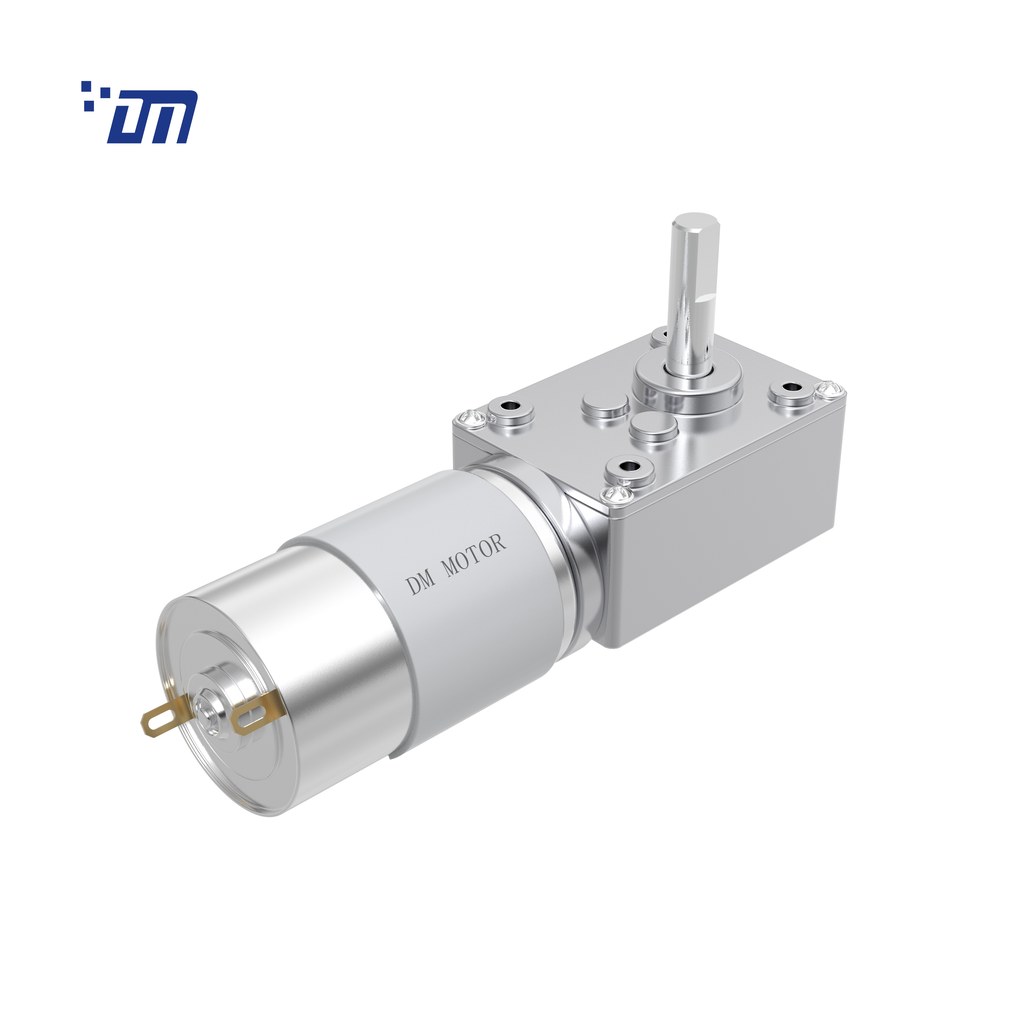
Uncouple the load and run the no-load test first: it splits the fault space in half in under five minutes.
Repair or Replace? What to Send the Manufacturer
Some faults justify a repair decision, others do not, and pretending otherwise wastes money:
- Replace the motor: burned windings, scored commutator, gearbox with collapsed teeth. On motors in this size class, the rebuild cost approaches the replacement cost.
- Repair in place: brush replacement, connector and cable service, supply-path fixes, cleaning and re-lubrication where the design allows.
- Resize, do not repair: thermal trips caused by genuine duty growth, and stall faults caused by application weight creep.
When a unit does go back to the factory, send the application, not just the motor. A bare motor on a bench tells the factory nothing. Include: rated voltage and the measured supply behavior under load, the load description and cycle rate, the ambient temperature, the symptom timeline, and the measurements from the sequence above — no-load current, terminal resistance readings, and the voltage at the motor terminals during a start attempt. That dataset lets the factory reproduce the fault on a dyno instead of guessing. If the diagnosis points at manufacturing rather than application, our technical support team takes the failure analysis from there.
FAQ
My DC gear motor hums but will not turn. Is the motor dead?
Usually not. Hum with a locked shaft means the winding is energized, so electrically the motor is alive — the shaft cannot turn. In order of probability: the load or gearbox is jammed, the output is blocked by a self-locking worm stage against a seized mechanism, or the motor is undersized for a load that has grown. Uncouple the load and retry no-load before replacing anything.
How do I tell a gearbox failure from a motor failure without disassembly?
Run the no-load test with the load uncoupled. If the motor spins freely at close to rated no-load speed with no-load current at or below the datasheet value, the motor and gearbox are healthy and the fault is in the load or the supply. If no-load current runs high with rough running, suspect gearbox damage or bearing wear. Terminal resistance while hand-rotating the shaft then confirms the electrical side.
What no-load current is “too high” for a small gear motor?
There is no universal number — use the unit’s own datasheet. A practical flag for the worm gear motor used in this article: the 24 V version specifies no-load current at or below 0.21 A, so a consistent reading above roughly double that, with the unit at rated voltage, indicates mechanical friction worth investigating. Compare against the same temperature and voltage, because no-load current rises slightly with temperature and falls with low supply.
The motor starts only if I spin the shaft by hand first. What failed?
On a brushed DC motor, that signature points to brushes or the commutator: dead spots on the commutator, or a brush worn to the point where it only contacts at certain shaft angles. The motor can produce torque only when the shaft rests where the brush still touches a live segment. Check brush length and freedom of movement, then inspect the commutator for dark or pitted bars.
Can a bad power supply damage a gear motor, not just stop it?
Yes, in two ways. Undervoltage makes the motor slip toward stall under load, and a stalled motor converts electrical input into heat rather than mechanical power, which ages the insulation system. Conversely, an unregulated supply that overshoots rated voltage raises speed and current beyond the design point. Regulate the supply within the motor’s rated voltage band and measure the sag under starting current before commissioning.
Related Reading
- How to Choose the Right Motor: A Guide from DongMing Motor
- How Noise and Vibration in DC Gear Motors Are Measured and Reduced
- Everything You Need to Know for DC Worm Gear Motor
- DC Motor vs DC Gear Motor: When Gearing Pays Off
- Our Quality Control Process
{acf_post_brief}