
How to Test a DC Motor: Bench Procedures and What to Measure
Most DC gear motor problems do not show up on a datasheet review. They show up on a bench. A motor that spins happily for ten seconds in a demo can drag a production line to a stop three weeks later because nobody ever measured its stall current, its temperature rise, or its actual no-load speed. Learning how to test a DC motor properly, with a bench power supply, a multimeter and a simple torque fixture, is the cheapest reliability program an OEM engineer can run.
This article walks through the bench procedures we use and recommend to customers: the no-load test, the locked-rotor (stall) test, load verification, temperature rise and insulation checks, and the noise and backlash inspections that buyers tend to skip. Every number below comes from real product tables for our DM-series gear motors, so you can compare the method against data you can actually request.
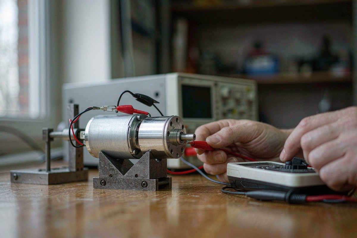
A current-limited supply, a meter and a rigid fixture are enough for a full bench session.
The Three Anchor Points Every DC Motor Curve Gives You
Before you touch a meter, know what the datasheet already tells you. A small DC gear motor’s performance table is built around three anchor points on the speed-torque line: no-load, maximum efficiency, and stall. If you have not read one of these tables before, our guide on how to read a motor datasheet explains the terminology in detail.
Here are three real examples from our catalog, with winding resistance derived from the stall data:
| Model | Type and ratio | Voltage | No-load (current / speed) | Stall current | Stall torque | Derived resistance |
|---|---|---|---|---|---|---|
| DM-22PM2140012056-107K | Brushed planetary, 107:1 | 12 V | 0.12 A / 56 rpm | 1.78 A | 4.3 kgf·cm | ≈ 6.7 Ω |
| DM-37SM55501216.2-178K | Brushed spur, 178:1 | 12 V | 0.15 A / 16.2 rpm | 2.86 A | 20.9 kgf·cm | ≈ 4.2 Ω |
| DM-58WM55502410.2-663K | Brushed worm, 663:1 | 24 V | 0.13 A / 10.2 rpm | 4.06 A | 46.1 kgf·cm | ≈ 5.9 Ω |
These three numbers matter because your bench measurements are judged against them. A motor whose no-load current comes in far above the datasheet ceiling is telling you about friction you have not found yet. A stall current far below the datasheet value usually means the winding has partially shorted turns or the magnets have been partially demagnetized by overheating. The derived resistance column is not printed on the datasheet; it comes from Ohm’s law at the stall point, and you will use it later to check whether your own sample matches the catalog winding.
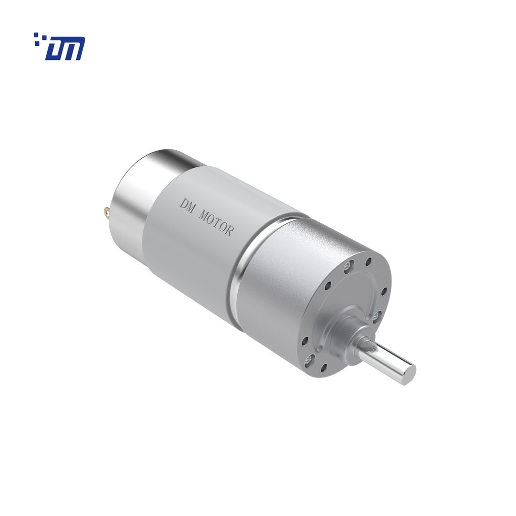
DM-37SM555: a 555-frame spur gear motor whose catalog anchors the table above.
Bench Setup: What You Need Before the First Measurement
A Current-Limited Power Supply, Not Just Any Bench Supply
The single most common bench mistake we see is testing stall behavior with a supply that cannot deliver the current. A locked 24 V worm gear motor draws 4.06 A at stall in the table above; a supply capped at 1 A will sag its output voltage, and you will record a stall current that says nothing about the motor. Set the supply’s current limit to roughly 1.5 times the expected stall current (about 6 A for the example above) and set the voltage to the rated value with the supply unloaded. Then measure voltage directly at the motor terminals, not at the supply front panel, so lead drop does not distort the reading.
For most small DC gear motors this means a supply rated in the 5–10 A range covers everything from 12 V planetary units to 24 V 555-frame worm drives. That is a modest investment compared with the cost of a mis-judged acceptance test.
Torque Measurement on a Realistic Budget
You do not need a dynamometer to get useful torque data. A lever arm clamped to the output shaft plus a digital kitchen scale or luggage scale gives you static torque to within a few percent: torque (N·m) = force (N) × arm length (m). A 10 cm arm reading 500 g on the scale gives 0.49 N·m, about 5 kgf·cm. The main discipline is to keep the arm horizontal at the moment of reading and to measure from the shaft center to the contact point, not to the end of the arm.
Fixturing and Run-In
Clamp the motor by its gearbox flange or mounting bosses, never by the bare motor can, and align any coupling so the shaft sees no side load. Before recording data, run the motor unloaded for five to ten minutes. Fresh grease redistributes and carbon brushes seat during the first minutes of operation; a motor measured cold out of the box will read a higher no-load current than it will after run-in, and that difference is acceptance noise, not a defect.
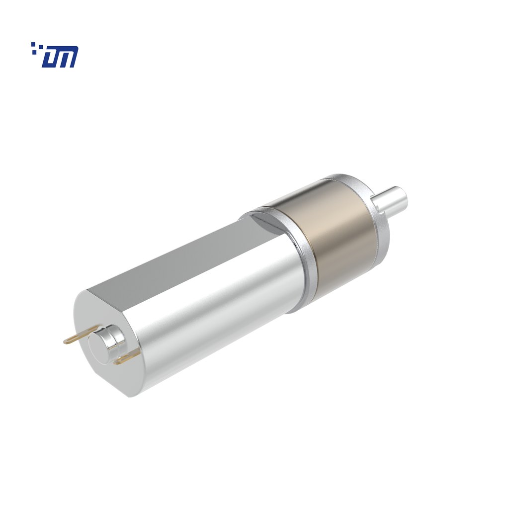
DM-22PM2140 planetary platform: five stages from 15.2 mm to 33.6 mm gearbox length.
No-Load Test: The Cheapest Health Indicator You Have
With the fixture ready, apply rated voltage and record no-load current and no-load speed after the run-in period. This is the cheapest test in the whole sequence, and in our experience it catches more problems than any other single measurement.
Reading the result takes some care. No-load current is dominated by friction: brush contact, bearing drag, and gear mesh losses multiplied through the ratio. The datasheet gives a ceiling (the DM-22PM2140 bare motor, for example, is specified at ≤ 80 mA no-load at 6000 rpm), and a sample that sits well above that ceiling after run-in is announcing a mechanical problem — a misaligned gear stack, a pinched bearing, grease that has migrated onto a friction surface, or a bent shaft from rough handling.
Speed matters as much as current. Compare the measured output speed against the expected value: motor no-load speed divided by the gear ratio. If a 6000 rpm motor on a 107:1 planetary gearbox turns only 48 rpm instead of about 56 rpm, the supply voltage at the terminals is sagging, the ratio does not match the order, or the motor is weak. Measure voltage at the terminals first, because supply lead drop under load is the classic false alarm.
Why No-Load Current Varies Between Samples
Two units of the same model will rarely show identical no-load current. Magnet strength tolerances, brush seating, and grease distribution all move the number. This is why a good acceptance criterion is a window, not a point value: reject samples above the datasheet ceiling, but do not expect every good sample to match the catalog figure to the milliamp.
Stall Test: Locked-Rotor Current and Winding Resistance
The stall test measures what the motor does at the other end of the curve, and it is the fastest way to verify the winding itself.
How to Hold a Stall Safely
Lock the output shaft (or the bare motor shaft for a gearbox-less unit), apply rated voltage for two to three seconds, and record the current. Two to three seconds is enough to get a stable reading and short enough that a small winding does not heat meaningfully. The locked rotor draws its full stall current the instant voltage is applied, and that current heats the winding at a rate proportional to the square of the current; holding a stall for tens of seconds on a 555-frame motor is a good way to turn a healthy sample into a scrap sample. Release, let the motor cool to ambient, and repeat once to confirm the reading is stable.
Deriving Winding Resistance and Checking the Speed-Torque Line
Divide terminal voltage by measured stall current to get the winding resistance. For the DM-58WM55502410.2-663K worm gear motor: 24 V ÷ 4.06 A ≈ 5.9 Ω. Your measured value should land close to the catalog-derived figure — within roughly 10–15% covers normal winding tolerance — and a sample that reads far higher has oxidized brush contact or a bad termination, while one that reads far lower has shorted turns.
Resistance also lets you sanity-check the whole speed-torque line without a dynamometer. The line runs from the no-load point to the stall point, and torque is very nearly proportional to current along it. If a customer reports that a motor stalls under a load the datasheet says it should handle, measure the current at that load and see where it sits between no-load and stall. In the worm motor above, a load drawing 2 A is at roughly (4.06 − 2.00) ÷ (4.06 − 0.13) ≈ 52% of stall torque, around 24 kgf·cm of output. That one calculation settles most “the motor is too weak” arguments in five minutes.
One caution: on a brushless unit, stall current is limited by the driver’s protection, not by the winding. Bench-test BLDC gear motors as a complete system with their driver, and never lock the rotor against a driver that is not configured for it.
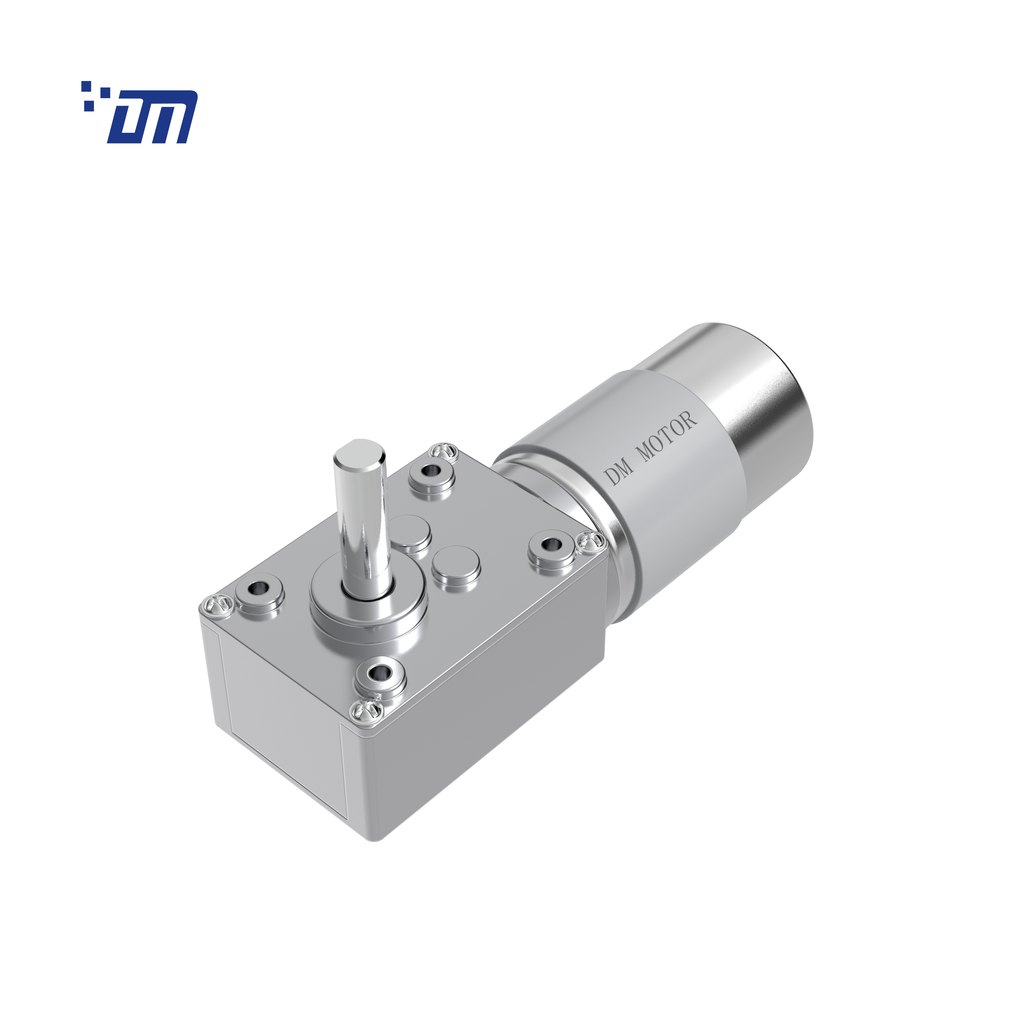
DM-58WM555 worm gear motor: the platform behind the worked example.
Load Verification: Checking the Point the Application Actually Lives At
Stall and no-load are the easy endpoints; your product spends its life between them. Apply a representative load with the lever-arm brake or a powder brake and verify two things.
First, verify the maximum efficiency point. The datasheet lists the current, speed and torque at max efficiency — 0.81 A at 8.6 rpm for the 24 V worm motor — and a sample that cannot reach approximately that torque at that speed has a gearbox or motor problem that endpoint tests missed. Second, verify the duty. A motor that survives a 30-second load test is not necessarily a motor that survives an S3 intermittent cycle at 40% duty for a shift; the heat from repeated starts accumulates in the gearbox grease and the winding, and our article on motor duty cycles (S1, S2 and S3) explains how to convert a real duty pattern into a test that represents it.
When a motor will be started under full load — a valve actuator against pressure, a lifting column from bottom position — replicate the worst case once on the bench, deliberately, with the current limit set high enough to see the real inrush. Field failures in these applications almost always start at the first start, not the thousandth; when one slips through anyway, our field guide for a DC motor that will not start walks the diagnostic sequence.
Temperature Rise and Insulation: The Checks That Predict Longevity
Run the motor at rated load and log case temperature with a thermocouple every few minutes until it plateaus. The practical limit is not the copper; it is the grease and the insulation class. Gearbox grease in small gear motors starts to degrade as it approaches the 80–90 °C range, which means the gearbox, not the winding, is usually the first thing to fail thermally in a compact drive — the same pattern behind most DC motor overheating cases we see. Insulation classes under IEC 60085 (for example class B at 130 °C or class F at 155 °C) set the winding’s ceiling, and IEC 60034-1 defines how temperature rise is evaluated for rotating machines; you do not need to run a full laboratory heat-run, but you should know which class your winding carries before you set an acceptance limit.
The insulation resistance check belongs at the end of the session: measure between winding terminals and the metal case at 500 V DC with the motor disconnected from any electronics. A new, dry winding measures tens to hundreds of megohms; a reading that has collapsed into the single digits means moisture, contamination, or damaged insulation, and the sample should be quarantined, not shipped. On brushless motors with a built-in driver, skip the megger entirely — applying 500 V DC into a board full of semiconductors destroys it, and this mistake is more common than it should be.
Noise, Vibration and Backlash: The Checks Buyers Forget Until the Line Complains
Electrical tests say nothing about whether the drive will annoy the user. After the thermal checks, listen to the motor at no-load and at application load, and measure sound pressure at a fixed distance if noise is a specification. Gear mesh whine, bearing rumble and brush hiss have distinct signatures; how gear motor noise and vibration are measured and reduced covers the measurement positions and the usual fixes.
Check gearbox backlash with a dial indicator on the output shaft with the motor held stationary: rock the shaft within the free play and read the angular or linear play. Worm gearboxes are effectively rigid in the back-driving direction, which is one reason lift and gate applications favor them; planetary stages carry more teeth in mesh and typically show less backlash per stage than a single spur stage of the same ratio. Whatever limit you set, set it in the purchase specification — backlash is invisible on a packing slip and expensive to discover in the field.
A Worked Example: One Bench Session for a 24 V Worm Gear Motor
Here is how the pieces fit together for DM-58WM55502410.2-663K, a 24 V worm gear motor on a 663:1 gearbox (a four-stage worm set with 40% gearbox efficiency and 15 N·m breaking torque):
| Step | Procedure | Datasheet reference | Acceptance logic |
|---|---|---|---|
| 1 | Supply set to 24 V, current limit 6 A (≈ 1.5 × stall) | Stall current 4.06 A | Limit above stall, voltage measured at terminals |
| 2 | Run-in 10 min unloaded, then no-load readings | No-load 0.13 A / 10.2 rpm | Current below datasheet ceiling; speed within window |
| 3 | Stall 3 s, record current | 4.06 A | Within ±20% of reference; R = 24 ÷ I ≈ 5.9 Ω check |
| 4 | Lever-arm torque at stall | 46.1 kgf·cm | Scale reading × arm length within ±20% |
| 5 | Load run at max-efficiency point | 0.81 A / 8.6 rpm | Sample reaches ≈ 46 kgf·cm band without stalling |
| 6 | Thermocouple run to plateau | Grease limit 80–90 °C | Case plateaus comfortably below the grease band |
| 7 | Insulation resistance, 500 V DC | — | Tens of megohms or higher on a dry winding |
A sample that passes all seven rows is very unlikely to surprise anyone downstream. Total bench time is under an hour, and every row can be written directly into an incoming inspection instruction.
Turning Measurements Into Acceptance Criteria
Once the procedure exists, the last step is contractual. Put the windows in the purchase specification or RFQ so both sides measure the same things the same way:
- No-load current: reject above the datasheet ceiling, measured after run-in, at rated terminal voltage.
- Stall current: we suggest a band of roughly ±20% around the datasheet value to cover magnet and brush tolerances; your QMS sets the final numbers.
- No-load speed: expressed as motor speed ÷ ratio, measured at the terminals, after run-in.
- Stall torque: lever-arm static value within the agreed band.
- Temperature rise: plateau below the grease band and within the winding’s insulation class margin.
- Insulation resistance: minimum megohm value agreed for the shipping condition.
We would rather agree on these windows before the first shipment than argue about a meter reading after it. If you are still selecting the motor itself, our guide on how to choose the right motor walks through the sizing side, and our DC spur gear motor range page lists the standard platforms these procedures apply to.
Frequently Asked Questions
How big should my bench power supply be for stall tests?
Size it for about 1.5 times the motor’s stall current. A 24 V worm gear motor with 4.06 A stall needs a supply comfortable at 6 A or more; a 12 V planetary with 1.78 A stall is fine on a 3 A supply. An undersized supply sags under locked-rotor load and produces stall readings that are meaningless.
Can I bench-test a BLDC gear motor the same way?
Only as a complete system. A brushless motor cannot run without its driver, so the stall current you measure is the driver’s protection limit, not the winding’s. Test with the specified driver, verify hall sensor or encoder feedback while rotating, and never connect a megger to a unit with electronics inside.
How long can I hold the rotor during a stall test?
Two to three seconds per attempt, then let the winding cool back to ambient. The winding heats at a rate proportional to the square of the current, and its resistance climbs as it warms, so a long stall reading drifts downward and teaches you nothing. Two confirming attempts after cool-down are enough.
What insulation resistance should a small DC gear motor show?
A new, dry winding measures tens to hundreds of megohms at 500 V DC between winding and case. The absolute value matters less than the collapse: a sample that once read high and now reads single-digit megohms has taken up moisture or damaged its insulation. Follow your own specification for the release threshold.
Why is my measured no-load speed lower than the datasheet?
Three usual causes: the datasheet no-load speed belongs to the bare motor, and output speed is that figure divided by the gear ratio; supply lead drop is pulling the terminal voltage below rated; and the sample has not been run in, so friction is still high. Measure terminal voltage first — it resolves the second cause in seconds.
Dongming Motor — https://szdmmotor.com
Precision DC gear motors, brushless planetary gear motors and custom drive solutions for OEM applications.