
BLDC Motor Controller Selection: Trapezoidal vs Sinusoidal Commutation
Two controllers, one 24 V brushless motor, same 1:36 planetary gearbox. On the bench one unit runs clean and quiet; the other growls from about 40 % load and pulls 3 percentage points more current doing the same work. Nothing changed in the motor. What changed is whether the BLDC motor controller commutates in six steps or drives sinusoidal phase current.
This article is for engineers specifying a motor and controller as a pair, and for buyers who have to justify the price difference between a six-step board and a field-oriented control (FOC) board. It covers what actually changes in the motor, the gearbox, the feedback sensor and the bill of materials — and the cases where paying for sinusoidal commutation buys nothing.
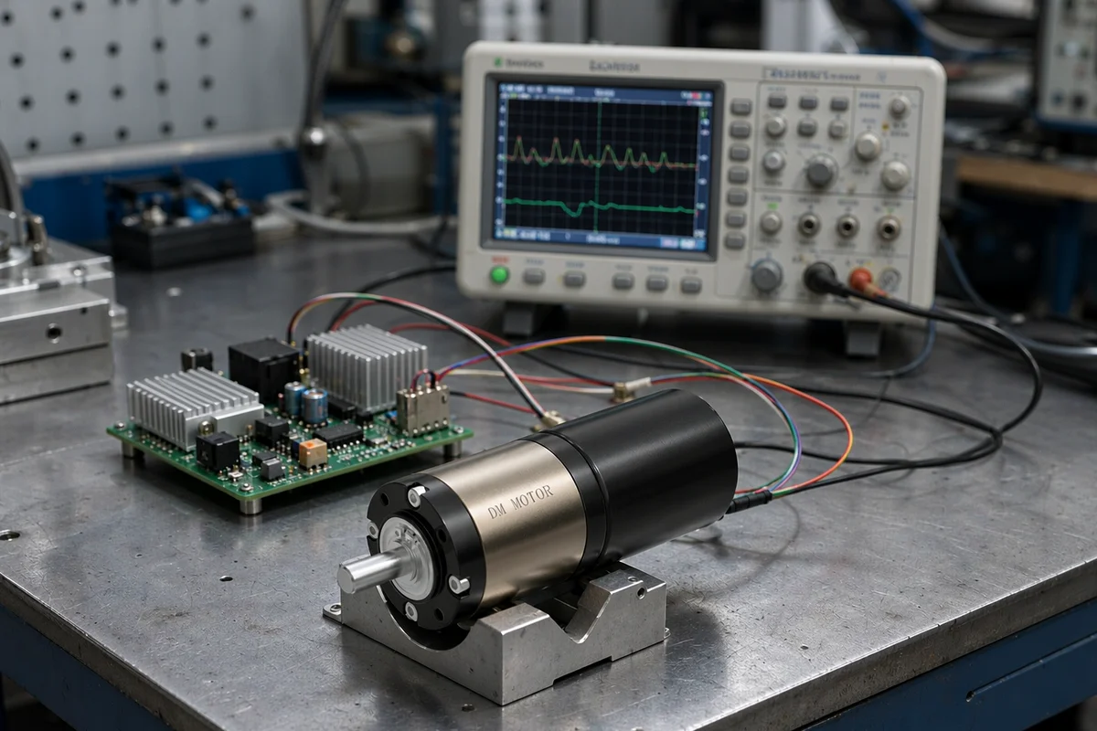
Commutation quality shows up on a loaded bench, not in a free-run test: current waveform, torque ripple and audible noise are measured with the gearbox loaded.
What the two commutation schemes do to the phase current
A three-phase brushless motor produces torque only where phase current and back-EMF line up. Every commutation scheme is a different answer to the same question: how precisely do you want to control that alignment?
Six-step keeps the current blocky on purpose
With three Hall sensors spaced 120 electrical degrees apart, the controller sees six distinct states per electrical revolution, one every 60 degrees. In each state it connects the DC bus across two phases and leaves the third floating, reading back-EMF on it if the drive is sensorless. Each phase conducts for 120 degrees, rests for 60, then conducts in the opposite direction.
The result is a current waveform with flat tops and hard edges. It is cheap to generate — an 8-bit microcontroller with a comparator and six MOSFETs is enough — and it stays stable at high speed because there is no current loop to fall behind. Switching frequencies for this class of drive typically sit at 8–16 kHz.
Sinusoidal drives three currents, not two
A sinusoidal (FOC) controller synthesizes three phase currents 120 degrees apart, each proportional to the torque demand. That requires a rotor angle accurate to a few electrical degrees, not 60. Inside the loop it runs Clarke and Park transforms, two current PI regulators and a space-vector modulator, and it usually switches at 16–20 kHz to keep the current ripple small and the switching noise out of the audible band where a gearbox would amplify it. The implementation detail is well documented in engineering notes such as Microchip AN1017 on sinusoidal control of a permanent magnet synchronous motor.
The trade is straightforward: smoother torque, more computation, and a rotor angle good enough to make the math worth doing.
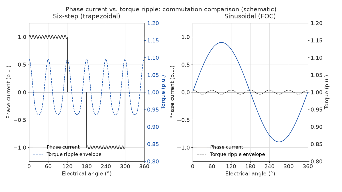
Same bus voltage, same motor: six-step delivers current in 120-degree blocks and the torque envelope oscillates; a sine drive holds the envelope close to flat.
Torque ripple is the number that decides whether anyone hears the motor
Six-step commutation produces torque ripple at six times the electrical frequency, because the current block changes six times per electrical revolution. With an ideal trapezoidal back-EMF the theoretical peak-to-peak ripple is about 13.4 %; real motors with slotted stators and non-ideal magnets typically land at 8–15 %.
A sinusoidal drive with a 1,000 CPR encoder commonly holds ripple at 2–4 %. With Hall sensors only, interpolation error usually pushes it back up to 5–8 %, which is the single most common disappointment in this category.
| Parameter | Six-step (trapezoidal) | Sinusoidal (FOC) |
|---|---|---|
| Phase current shape | 120° blocks, 60° off per phase | Continuous sinusoidal, 120° apart |
| Rotor angle resolution needed | 60 electrical degrees (3 Halls) | 1–5 electrical degrees (encoder or observer) |
| Torque ripple, peak-to-peak | 8–15 % | 2–4 % with encoder, 5–8 % with Halls only |
| Ripple frequency | 6 × electrical frequency | 6th harmonic only, strongly attenuated |
| Typical PWM frequency | 8–16 kHz | 16–20 kHz |
| Audible noise at same load | Reference | 3–6 dBA lower on a geared unit |
| Efficiency at 25 % rated load | Reference | 2–4 points higher |
| Efficiency at 100 % rated load | Reference | 0.5–1.5 points higher |
| Controller cost at 24 V / 10 A | Reference | USD 3–8 more per unit at volume |
| Feedback required | 3 Halls, or sensorless back-EMF | 3 Halls + encoder / resolver, or observer |
| Behaviour at 20,000 rpm | Stable, simple | Demanding on sampling and CPU headroom |
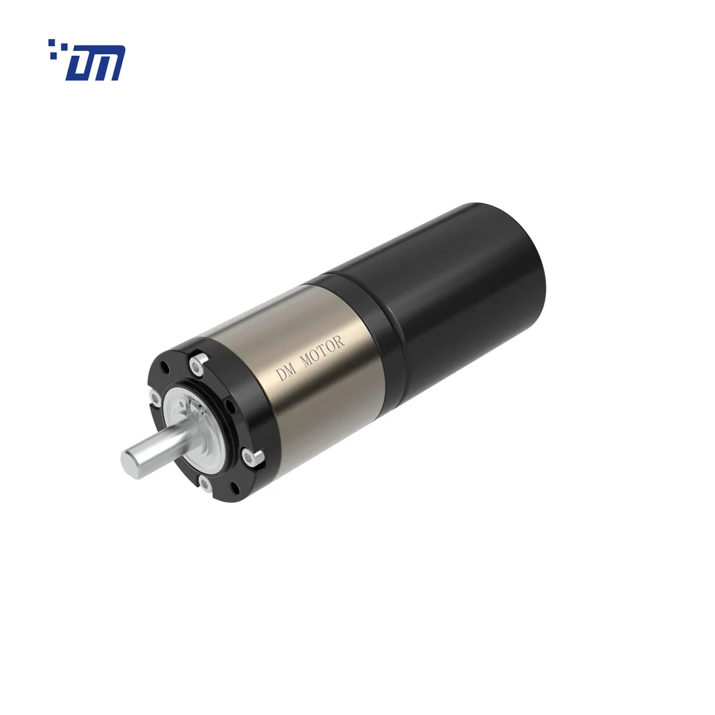
The motor that makes the choice concrete: 42 mm frame, planetary stage, Hall feedback — the configuration where a sine controller adds value only if the gearbox needs it.
Where trapezoidal commutation still wins
Six-step is not the obsolete option. For fans, pumps, and any load where inertia smooths the ripple, it is the rational choice, and we tell customers so even though a sine drive is the more expensive product.
Three cases where we keep six-step:
High-speed, low-inertia loads. Above roughly 15,000 rpm the electrical frequency climbs past 1 kHz on a 4-pole-pair motor. A sinusoidal current loop then needs a sampling rate and CPU headroom that add cost without adding value, because the mechanical time constant already filters the ripple.
Cost-driven, high-volume appliances. At 100k units a year the USD 3–8 controller delta is the whole margin. A coffee grinder running 8 seconds per cycle does not care about 12 % torque ripple.
Harsh electrical environments. Six-step drives tolerate Hall jitter and cable capacitance better. We have seen sine drives trip on encoder noise from a 2 m unshielded motor cable in a welding cell, where the six-step unit on the same machine ran without fault.
The honest trade: what you give up is low-speed smoothness and about 2–3 points of efficiency at part load. If the application never runs below 30 % speed, that trade is usually fine.
Why the gearbox changes the answer
A gearmotor is not a motor plus a passive box. The gearbox multiplies torque ripple by the ratio, adds its own transmission error, and — this is the part that gets missed — has structural resonances that ripple harmonics can excite.
Ripple frequency versus gear mesh frequency
Take a 4-pole-pair motor at 3,000 rpm. Electrical frequency is 200 Hz, so six-step ripple sits at 1.2 kHz. Run it through a 1:36 planetary stage with a 12-tooth sun gear: output speed is about 83 rpm and the sun gear meshes at 600 Hz. The two frequencies are far apart, and that unit sounds acceptable even on six-step.
Change the ratio to 1:100 and drop the motor to 1,500 rpm for the same output speed. Now the ripple moves to 600 Hz while the mesh stays near 300 Hz — and the second harmonic of the mesh lands at 600 Hz. On small planetary units the housing and gear-train resonances we see on the bench usually sit somewhere in the 300–900 Hz band, so the same motor and a different ratio can produce a completely different noise signature.
That is why “this motor is quiet” is not a transferable statement. Noise is a property of the motor–gearbox–mounting combination at a specific speed.
Ripple is also a backlash problem
In a low-backlash gearbox, torque ripple makes the teeth cross the backlash zone six times per electrical revolution. At 30 rpm output you hear it as a tick, not a hum. On a positioning axis it shows up as a limit cycle: the load cell or encoder sees ±0.1° of oscillation that no amount of gain tuning removes, because the disturbance is generated inside the drive train.
If the axis has to hold position within 0.05°, plan for sinusoidal commutation. If it only has to move and stop, six-step with a friction-loaded output is usually enough.
Commutation and feedback have to be chosen together
The most expensive mistake in this category is pairing a sine controller with Hall-only feedback and expecting encoder-grade smoothness.
- Three Halls only. 60-degree sectors. A sine drive can interpolate between edges, but position error inside each sector is real, and torque ripple stays at 5–8 %.
- Incremental encoder, 500–1,000 CPR. Enough for FOC at low speed, and the standard choice for gearmotors that must run below 50 rpm output.
- Sensorless observer. Works well above 10 % of rated speed. Below that, back-EMF is too small to estimate from, and startup is open-loop — fine for a pump, wrong for a valve actuator that must break away a sticky stem.
For a deeper comparison of sensor options and their failure modes, see our breakdown of Hall effect sensors versus encoders in BLDC motors.
My position on this: if the budget only covers Halls, buy a six-step controller and spend the savings on bearings and a better gearbox. A sine drive interpolating three Halls is the worst of both — you pay FOC prices for interpolation-grade torque.
Efficiency: the 2–4 point gap and where it comes from
Efficiency claims in this category are hard to compare because the boundary of the measurement is rarely stated. IEC 60034-2-1 defines how losses in rotating electrical machines are determined; when a datasheet quotes “88 % efficiency” for a motor plus controller, ask whether controller losses are inside that number. Often they are not.
Where the difference between six-step and FOC actually comes from:
- Copper losses from current harmonics. Six-step current has significant harmonic content; I²R loss scales with the square of RMS current, so a 15 % THD adds roughly 2 % to winding loss before anything else happens.
- Dead time. At 20 kHz with 1 µs of dead time, roughly 2 % of the volt-second product is lost per switching event. Below 1 µs the shoot-through risk goes up, so this is a real design trade, not a free win.
- Switching losses. Doubling PWM frequency roughly doubles switching loss in the MOSFETs. The 8 kHz to 20 kHz move costs efficiency even as it buys smoothness; that is why sine drives at 48 V sometimes measure worse than a well-tuned six-step unit at full load.
- Iron and eddy losses. Lower current harmonic content means less high-frequency flux in the stator, which matters most in thin-lamination, high-speed designs.
At 25 % of rated load — where most gearmotors actually run — the gap typically measures 2–4 points in favour of FOC. At rated load it narrows to 0.5–1.5 points.
Which scheme fits which application
| Application | Typical output speed | Ripple tolerance | Recommended |
|---|---|---|---|
| AGV / AMR wheel drive | 60–150 rpm | Low (velocity loop) | Sinusoidal with encoder |
| Valve and damper actuator | 5–30 rpm | Medium (position hold) | Sinusoidal with encoder |
| Conveyor drive | 30–120 rpm | High | Six-step, sensorless |
| Medical peristaltic pump | 50–300 rpm | Very low (flow pulsation) | Sinusoidal with encoder |
| Power tool / appliance | 1,000–20,000 rpm | High | Six-step |
| Robot joint | 10–60 rpm | Very low (backlash) | Sinusoidal with encoder |
Worked example: 24 V, 1:36 planetary gearmotor on an AGV drive
Motor: 3,000 rpm no-load, 0.8 kgf·cm rated torque, 4 pole pairs. Gearbox: 1:36 planetary, 90 % efficiency. Output: 83 rpm and roughly 26 kgf·cm continuous.
Load check. A 40 kg platform on 125 mm wheels, 0.3 m/s² acceleration: 12 N of accelerating force plus about 8 N of rolling resistance, so 20 N total, or about 1.25 N·m at the wheel — 6.4 kgf·cm per wheel with two driven wheels. The 26 kgf·cm rating leaves a 4× margin, which is the margin you want for carpets, ramps and a 30 % grade.
Current check. Winding resistance 1.2 Ω at 24 V gives a stall current near 20 A. The controller must be rated for that inrush even though continuous current is 4–5 A. Sizing a controller at 10 A continuous and 12 A peak is the classic failure we see in RFQs: it survives the datasheet duty cycle and dies on the third ramp on a slope.
Ripple check. Six-step at 3,000 rpm puts 13 % torque ripple at 1.2 kHz into a 1:36 gearbox. The wheel encoder then reports 3–5 % velocity jitter, and the AGV’s position loop starts hunting at low speed. This is the case where the extra USD 5 for FOC is not a luxury — it removes a tuning problem that never goes away otherwise.
Five selection mistakes we see in RFQs
- Sizing on continuous current only. Peak must cover stall for 1–2 seconds, at 1.5–2× the continuous rating.
- Ignoring motor inductance. Low-inductance motors (under 100 µH) need higher PWM frequency or external chokes, otherwise current ripple alone can exceed 30 %.
- Buying “sinusoidal” for a Hall-only motor. You get interpolation, not FOC. Budget for the encoder or stay six-step.
- Forgetting thermal coupling. Controller losses end up in the same housing as the gearbox. A 10 W controller loss inside a sealed 100 mm housing raises internal temperature by 8–12 °C, which then derates the grease.
- Comparing voltage, not current. A 48 V-rated board on a 24 V system is fine electrically but wastes ADC resolution on current sensing, which shows up as coarse low-speed behaviour.
Specification checklist for a BLDC controller
Put these ten lines in the RFQ and most of the ambiguity disappears:
- Continuous and peak current, with peak duration in seconds
- Bus voltage range, including brown-out behaviour
- Commutation scheme, and whether FOC runs on Halls alone or requires an encoder
- PWM frequency and current-loop bandwidth
- Feedback interface: Hall, incremental encoder, absolute, or sensorless
- Required speed regulation at the lowest operating point
- Torque ripple target at that same point
- Operating temperature with the controller mounted in the final enclosure
- Protection set: over-current, over-voltage, stall detection, thermal
- Whether efficiency figures include controller losses
If you are still comparing candidate motors for the same axis, the datasheet reading guide on stall torque and the rated point explains which four numbers to compare before you get to the controller question. And if the drive train is still open, our overview of BLDC planetary gear motor types and their functions covers how stage count and winding choice interact with commutation.
Frequently asked questions
Can a sinusoidal controller run on a motor with only three Hall sensors?
Yes, but with interpolation rather than true field orientation. Torque ripple typically stays at 5–8 % instead of 2–4 %, and low-speed smoothness improves only marginally. If the application runs below 50 rpm output, add an encoder.
Is six-step always louder than FOC?
On a bare motor the difference is usually 3–6 dBA. On a geared unit it depends on whether the ripple harmonic lands near a structural resonance — the same motor can sound acceptable on one ratio and noisy on another. Measure the assembled gearmotor, not the motor alone.
Does FOC add cost per unit?
At 24 V and 10 A, roughly USD 3–8 per controller at volume: a faster MCU, an encoder interface, and more engineering time in the current loop. That is small against a positioning problem, and large against a 100k-unit appliance program.
Which scheme suits a gearmotor running at 30 rpm output?
Sinusoidal with an encoder, in most cases. At that speed six-step ripple becomes visible as cogging-like motion and audible as a tick each commutation. The exception is a friction-loaded application where position does not matter.
Do I need an absolute encoder for FOC?
No. An incremental encoder with an index pulse is enough; the index gives you a repeatable zero at power-up homing. Absolute encoders are worth it when the axis must know position before any motion, which is a system requirement, not a commutation one.
If you are matching a brushless motor to a gearbox and a drive for a specific duty cycle, our engineering team can review the load case against the BLDC planetary gear motor range or the brushless DC motor range, and we will say when six-step is the better answer. Units are built and tested against the process described in our quality control procedure, and motor life at the rated point is covered in how to extend BLDC motor lifespan.
{acf_post_brief}