
Hall Effect Sensors vs Encoders in BLDC Motors: Differences Explained
1. Introduction
A BLDC motor requires rotor position information to achieve proper electronic commutation and efficient closed-loop control. Two common feedback technologies are Hall effect sensors and encoders.
Although both can provide rotor position information, they serve different control requirements.
For applications such as fans, pumps, actuators, AGVs, robotic joints, and precision motion systems, selecting the right feedback device can directly affect starting reliability, speed regulation, positioning accuracy, torque ripple, and system cost.
The key difference is simple: Hall sensors provide relatively coarse rotor position information, while encoders provide much higher-resolution position and speed feedback.
2. How Hall Effect Sensors Work in a BLDC Motor
A Hall effect sensor detects changes in magnetic flux and converts them into electrical signals.
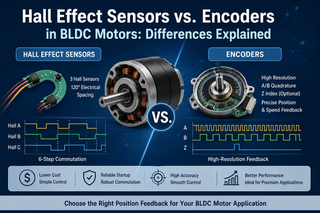
In a typical three-phase BLDC motor, three Hall sensors are positioned around the stator, usually with approximately 120° electrical separation. As the permanent-magnet rotor rotates, the magnetic field changes around each sensor. The Hall devices generate digital signals such as Hall A, Hall B, and Hall C.
The motor controller uses these signals to determine the approximate rotor position and select the appropriate MOSFET switching sequence.
For conventional six-step BLDC control, the three Hall signals generate six valid commutation states per electrical cycle. Hall sensors are therefore well suited to basic BLDC commutation, speed feedback, direction detection, and reliable startup.
3. How Encoders Work in BLDC Motors
An encoder measures shaft or rotor position with much finer resolution. Depending on the design, a BLDC motor may use an incremental optical encoder, magnetic encoder, or absolute encoder.
An incremental encoder commonly provides A/B quadrature signals and sometimes a Z index signal. For example, an encoder rated at 1,000 pulses per revolution (PPR) can generate 4,000 counts per revolution with 4× quadrature decoding.
This higher resolution allows the controller to calculate shaft position and speed more precisely, making encoders suitable for servo systems, robotic joints, CNC equipment, AGV/AMR drive systems, precision actuators, and industrial automation.
4. Hall Sensor vs Encoder: Key Differences
The biggest practical differences are resolution, control accuracy, complexity, and cost. Higher resolution does not automatically mean better for every BLDC application. If the application only requires basic speed regulation and reliable commutation, an encoder may add unnecessary cost and complexity.
5. Position Resolution: The Biggest Difference
A typical three-Hall BLDC system divides electrical rotation into six commutation sectors. The controller therefore knows the approximate rotor position but not the exact shaft angle.
An encoder can provide hundreds, thousands, or even millions of position counts per mechanical revolution, depending on encoder type and decoding method. This makes encoder feedback much more suitable for precise BLDC motor position control.
6. Hall Sensors Are Better for Cost-Sensitive BLDC Motors
One major advantage of Hall sensors is their low system cost. A basic Hall-based BLDC system generally consists of a BLDC motor, three Hall sensors, an MCU, and a MOSFET driver.
For cooling fans, small pumps, electric valves, automotive actuators, smart locks, electric curtains, and consumer appliances, this level of feedback can be sufficient when positioning accuracy is not critical.
7. When Should You Use an Encoder?
An encoder becomes more valuable when the application requires accurate shaft position or very stable low-speed operation.
For a robotic joint, for example, Hall feedback may not provide sufficient resolution when the output shaft must be positioned within a small angular tolerance. Encoder feedback lets the controller continuously compare actual position with target position and adjust motor current accordingly.
8. Hall Sensors vs. Encoders for BLDC Commutation
Hall sensors are particularly convenient for six-step commutation. The controller reads the Hall states and determines which motor phases should be energized.
Advanced control methods such as FOC (Field-Oriented Control) can benefit from higher-resolution rotor position feedback. An encoder can provide more accurate electrical angle information, improving torque smoothness, low-speed control, dynamic response, position accuracy, and current regulation.
9. Does a BLDC Motor Need Both Hall Sensors and an Encoder?
Not necessarily. In some systems, both are used: Hall sensors provide reliable commutation or startup information, while the encoder provides high-resolution position and speed feedback.
This architecture can be useful when high-performance control, reliable startup, or feedback redundancy is required. However, additional sensors increase BOM cost, wiring, assembly requirements, and software complexity.
10. Hall Sensor or Encoder: How Engineers Should Choose
Choose Hall sensors when cost is a major constraint, six-step commutation is sufficient, position accuracy is not critical, moderate speed regulation is acceptable, or compact electronics are required.
Choose an encoder when precise position control, very low-speed operation, high-resolution speed feedback, smooth torque, servo operation, robotics, or industrial automation is required.
Consider both when the system has demanding performance requirements, reliable startup is important, or redundant feedback is valuable.
11. Important Motor Design Considerations
Sensor selection should not be separated from electromagnetic and mechanical design.
Electrical and mechanical angle are related by θe = p × θm, where θe is electrical angle, θm is mechanical angle, and p is the number of pole pairs.
Encoder resolution should be selected according to positioning accuracy, gearbox ratio, and control architecture. Encoder location also matters: a motor-side encoder measures motor shaft position, while an output-side encoder can directly measure output position. In systems with gearbox backlash or elastic deformation, output-side feedback can provide a significant control advantage.
12. Hall Sensor vs Encoder for Geared BLDC Motors
For a BLDC gear motor, the gearbox should be treated as part of the feedback system.
For example, if motor speed is 3,000 RPM and the gear ratio is 30:1, output speed is approximately 100 RPM. A motor-side encoder can measure the motor shaft accurately, but it cannot directly compensate for mechanical backlash between gearbox and output shaft.
If precise output positioning is required, an output encoder may therefore be preferable. This is particularly relevant to robotic joints, AGV steering systems, electric actuators, smart locks, and precision valve actuators.
13. Hall Sensors vs Encoders: Cost vs Performance
There is no universally better sensor. Hall sensors generally offer lower cost, simple control, and sufficient feedback for many applications. Encoders provide higher resolution and are more appropriate for precise motion control.
For high-volume consumer products, an encoder may add unnecessary cost. For a precision robotic actuator, the additional encoder cost can be justified by improved position accuracy, torque control, and system responsiveness.
14. Conclusion
The difference between Hall effect sensors and encoders in BLDC motors mainly comes down to feedback resolution and control requirements.
Hall sensors are an excellent solution for low-cost BLDC commutation, speed feedback, and reliable startup. Encoders provide much more detailed rotor or shaft position information and are better suited for precision BLDC motor control, servo applications, robotics, and industrial automation.
For engineers selecting a custom BLDC motor, the sensor should be specified together with the motor winding, pole-pair count, gearbox ratio, driver, control algorithm, operating speed, torque, and required positioning accuracy.
The best solution is not necessarily the highest-resolution sensor—it is the sensor that provides the required control performance without unnecessary system cost and complexity.
Hall Sensor vs Encoder Comparison
| Parameter | Hall Effect Sensor | Encoder |
| Position resolution | Low | High |
| Typical feedback | Rotor sector | Precise shaft position |
| BLDC commutation | Excellent for six-step control | Excellent, especially with advanced control |
| Speed feedback | Basic | High precision |
| Position control | Limited | Excellent |
| Startup detection | Excellent | Depends on encoder type |
| Cost | Low | Medium to high |
| Electronics | Simple | More complex |
| Typical applications | Fans, pumps, simple actuators | Robotics, servo, automation |
FAQ
Can a BLDC motor work without Hall sensors?
Yes. A BLDC motor can operate using sensorless back-EMF detection or other estimation algorithms. Sensorless control can be more challenging at very low speed and during startup.
Are encoders more accurate than Hall sensors?
Yes. Encoders generally provide much higher position resolution than conventional Hall sensors, making them more suitable for precise position and speed control.
Are Hall sensors cheaper than encoders?
Generally, yes. Hall sensors usually have lower component and implementation costs, making them attractive for cost-sensitive BLDC applications.
Can Hall sensors be used with FOC?
Yes. Hall sensors can provide rotor position information for FOC, but their relatively low resolution can limit angle accuracy, particularly at low speed. Higher-resolution magnetic or optical feedback can improve FOC performance.
Which is better for a BLDC robotic joint?
For a precision robotic joint, an encoder is generally preferable because high-resolution position feedback enables more accurate torque, speed, and position control. Hall sensors may also be retained for commutation or startup redundancy.
Related reading
{acf_post_brief}