
How Noise and Vibration in DC Gear Motors Are Measured and Reduced
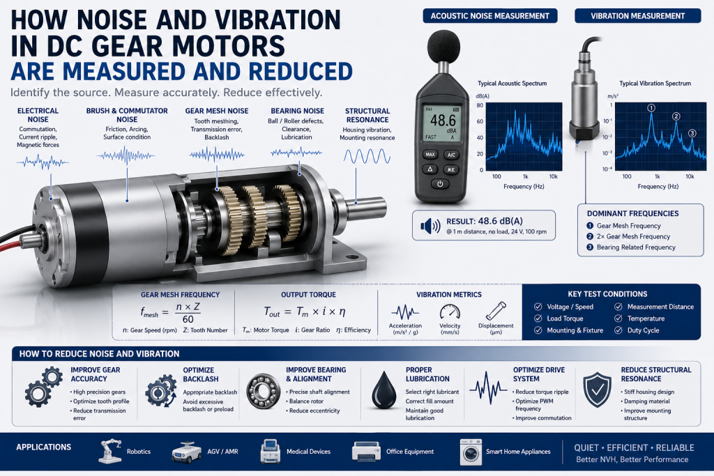
Noise and vibration are two important performance indicators when selecting a DC gear motor for robotics, automation equipment, medical devices, smart appliances, and other noise-sensitive applications.
A gear motor may meet its rated speed and torque requirements but still fail an application because of excessive acoustic noise, gear whine, vibration, or resonance.
For engineers, the key question is not simply “How loud is the motor?” but:
Where does the noise originate, how is it measured, and which design parameter should be changed to reduce it?
The main sources are usually the motor electromagnetic system, brushes and commutator, gears, bearings, shaft imbalance, and the motor/gearbox housing. Research on DC motor NVH has also identified brush-commutator interaction, gear/worm meshing, and the shaft-bearing system as major excitation sources.
1. What Causes Noise and Vibration in a DC Gear Motor?
A DC gear motor contains several potential vibration and noise sources.
1.1 Brush and Commutator Noise
In a brushed DC motor, the brushes continuously contact the commutator.
Small variations in:
Brush contact pressure
Commutator surface condition
Brush material
Commutation timing
Armature imbalance
Electrical current
can generate mechanical vibration and acoustic noise.
Poor commutation can also produce electrical torque ripple, which can excite mechanical resonances.
For applications requiring very low noise, a BLDC gear motor can eliminate mechanical brush/commutator contact, although electromagnetic torque ripple and switching-related noise still need to be considered.
2. Gear Mesh Is Often the Dominant Noise Source
In a DC gear motor, the gearbox frequently contributes more noise than the motor itself.
As gear teeth enter and leave mesh, the stiffness of the gear pair changes periodically. Manufacturing errors, tooth deformation, alignment errors, and transmission error can create periodic excitation at the gear mesh frequency.
The basic gear mesh frequency can be estimated as:
fmesh=n×Z60f_{mesh}=\frac{n\times Z}{60}
Where:
fmeshf_{mesh} = gear mesh frequency, Hz
nn = gear rotational speed, rpm
ZZ = number of teeth
For example, if a gear rotates at 1,500 rpm and has 20 teeth:
fmesh=1500×2060=500 Hzf_{mesh}=\frac{1500\times20}{60}=500\,Hz
If a strong acoustic or vibration peak appears around 500 Hz and its harmonics, gear meshing becomes a strong candidate for the noise source.
This is much more useful than simply listening to the motor and guessing where the noise comes from.
3. Backlash Can Produce Rattle and Impact Noise
Gear backlash is necessary for proper gear operation, thermal expansion, and lubrication. However, excessive backlash can increase impact noise, particularly during:
Low-load operation
Speed changes
Start/stop cycles
Forward/reverse switching
Load reversal
When the driving and driven teeth repeatedly separate and impact each other, the resulting vibration can become clearly audible.
However, reducing backlash excessively is not always a solution. Insufficient backlash can increase friction, heat generation, tooth interference, and wear.
Therefore, the correct engineering target is controlled backlash, not simply minimum backlash.
4. Bearing, Shaft and Assembly Errors
Bearings and shafts form the mechanical transmission path between the motor, gearbox, and housing.
Typical vibration sources include:
Shaft eccentricity
Rotor imbalance
Bearing clearance
Bearing preload
Shaft misalignment
Gear eccentricity
Poor gearbox assembly
Output shaft radial load
A gearbox can therefore produce excessive vibration even when the individual gears meet dimensional specifications.
For this reason, DC gear motor vibration measurement should be performed on the complete motor/gearbox assembly rather than only on individual components.
5. How Is DC Gear Motor Noise Measured?
There are two fundamentally different measurements:
Acoustic Noise
Measured using a microphone or sound level meter.
Typical parameters include:
Sound pressure level, dB(A)
Sound power level, dB
Frequency spectrum
Tonal peaks
Mechanical Vibration
Measured using an accelerometer.
Typical parameters include:
Acceleration, m/s² or g
Velocity, mm/s
Displacement, μm
Frequency spectrum
RMS vibration
Peak vibration
These measurements answer different questions.
Microphone: How much sound reaches the surrounding environment?
Accelerometer: How much mechanical vibration is generated by the motor and transmitted through the structure?
IEC 60034-9 specifies methods for determining sound power levels and noise limits for certain rotating electrical machines, while IEC 60034-14 covers vibration measurement and evaluation for specified larger machines. Importantly, IEC 60034-9’s scope is for machines from 1 kW upward, and IEC 60034-14 applies to machines with shaft heights of 56 mm and above, so these standards should not automatically be treated as acceptance limits for small micro DC gear motors.
For small DC gear motors, manufacturers should instead establish an application-specific test method and reference sample.
6. Use FFT and Order Analysis to Find the Noise Source
A simple dB measurement tells you how much noise exists.
FFT analysis helps determine why it exists.
A typical vibration or acoustic spectrum may contain:
| Frequency Component | Possible Source |
| 1× shaft speed | Rotor imbalance, eccentricity |
| 2× shaft speed | Misalignment or mechanical asymmetry |
| Gear mesh frequency | Gear tooth meshing |
| Gear mesh harmonics | Gear profile/mesh excitation |
| Broad high-frequency noise | Bearing or friction-related source |
| Commutation-related components | Brush/commutator system |
| Narrow resonance peak | Housing or structural resonance |
The exact diagnosis depends on motor speed, gear tooth count, load, and construction.
For engineering troubleshooting, order analysis is particularly useful because it links vibration frequencies to rotational speed rather than relying only on fixed-frequency measurements.
7. Test the Motor Under the Same Operating Conditions
One of the most common mistakes in DC gear motor noise testing is comparing motors under different conditions.
Noise can change significantly with:
Voltage
Speed
Output torque
Load inertia
Gearbox orientation
Mounting structure
Temperature
PWM frequency
Acceleration/deceleration
A practical test specification should define at least:
Voltage + Speed + Load Torque + Mounting + Distance + Measurement Position + Temperature
For example:
24 V / 100 rpm / 1.0 Nm output load / rigid fixture / 25°C / microphone at 1 m
This creates a repeatable baseline for supplier comparison.
8. How to Reduce DC Gear Motor Noise and Vibration
Noise reduction should normally follow a source → transmission path → radiation approach.
8.1 Improve Gear Accuracy
Gear manufacturing accuracy has a direct influence on gear mesh excitation.
Important parameters include:
Tooth profile accuracy
Tooth pitch accuracy
Surface roughness
Gear eccentricity
Center distance
Tooth alignment
Improved machining tolerances and appropriate tooth geometry can reduce transmission error and gear noise.
For high-performance gear motors, tooth profile and lead modifications can also be used to control load distribution and reduce dynamic excitation.
8.2 Optimize Gear Backlash
Too much backlash can create rattle and impact noise.
Too little backlash can increase friction and risk of interference.
The optimum backlash depends on:
Gear module
Gear material
Operating speed
Load
Temperature
Manufacturing tolerance
Lubrication
Therefore, backlash should be specified as an engineering tolerance, rather than simply asking a supplier for “zero backlash.”
8.3 Improve Bearing and Shaft Alignment
Reducing eccentricity and misalignment can significantly reduce vibration.
During assembly, control:
Bearing seat concentricity
Gear shaft alignment
Gear center distance
Output shaft runout
Bearing preload
Housing dimensional tolerance
A motor with excellent gears can still become noisy if the gearbox assembly introduces shaft misalignment.
8.4 Select the Right Lubricant
Gearbox lubrication affects both friction and acoustic behavior.
The lubricant should be selected according to:
Gear material
Gear speed
Load
Temperature
Gearbox volume
Expected lifetime
Too little lubricant increases friction and wear.
Too much lubricant can increase churning losses and temperature.
For small planetary or spur gearboxes, the lubricant type and filling quantity should therefore be validated through actual life and noise testing rather than selected only by viscosity.
9. Optimize the Motor Drive System
For brushed DC motors, commutation quality is important.
For BLDC gear motors, additional factors include:
PWM frequency
Hall sensor timing
Commutation strategy
Current ripple
Torque ripple
Control-loop parameters
A BLDC motor can be mechanically quieter because it eliminates brush/commutator contact, but poorly optimized electronic commutation can still produce audible tonal noise.
Therefore, quiet BLDC gear motor design requires both mechanical and electrical optimization.
10. Avoid Housing Resonance
A frequently overlooked issue is the motor mounting structure.
The motor may generate relatively low vibration, but the housing or mounting plate can amplify it through resonance.
The vibration path is typically:
Gear Mesh → Shaft/Bearing → Gearbox Housing → Mounting Structure → Airborne Noise
The gearbox housing therefore acts as an acoustic radiator.
Changing:
Housing thickness
Housing material
Rib structure
Mounting stiffness
Mounting location
Isolation material
can shift structural natural frequencies and reduce acoustic radiation.
This is why a motor that is quiet on a laboratory fixture can become noticeably louder after installation into a thin metal enclosure.
11. Practical Engineering Troubleshooting Procedure
When a customer reports excessive DC gear motor noise and vibration, use the following sequence:
Step 1 — Establish a Reference
Test a known-good motor using exactly the same voltage, speed, load, fixture, and temperature.
Step 2 — Separate Motor and Gearbox Sources
Compare:
Motor without gearbox
Complete gear motor
Different gearbox ratio
If the motor is quiet but the assembled gear motor is noisy, investigate the gearbox.
Step 3 — Perform FFT Analysis
Identify whether the dominant frequency follows:
Motor speed
Gear output speed
Gear mesh frequency
Commutation frequency
Step 4 — Check Mechanical Assembly
Inspect:
Shaft runout
Gear backlash
Bearing clearance
Gear alignment
Housing deformation
Fastener looseness
Step 5 — Test Different Loads
Measure noise at no load, rated load, and representative application load.
This is particularly important because some gear motors exhibit different noise characteristics under unloaded and loaded conditions.
12. What Engineers Should Specify When Purchasing a Low-Noise DC Gear Motor
Instead of asking a supplier:
“Can you provide a quiet DC gear motor?”
provide measurable requirements.
A good RFQ should include:
| Parameter | Recommended Specification |
| Rated voltage | e.g. 12 V / 24 V |
| Output speed | Required rpm |
| Continuous torque | Nm or kgf·cm |
| Peak torque | Nm or kgf·cm |
| Noise limit | dB(A), test condition defined |
| Vibration | RMS or peak value |
| Load condition | Defined output torque |
| Measurement distance | e.g. 0.5 m or 1 m |
| Mounting fixture | Defined |
| Operating temperature | °C |
| Duty cycle | Continuous / intermittent |
| Lifetime | Hours or cycles |
| Backlash | Maximum allowable value |
The most important point is that noise specifications must include test conditions.
“≤50 dB” has limited engineering meaning unless the measurement distance, load, speed, environment, and measurement method are also defined.
Conclusion
Reducing DC gear motor noise and vibration requires more than simply adding lubricant or selecting a larger motor.
The correct approach is:
Measure → Identify Frequency → Locate Source → Optimize Design → Validate Under Real Load
For gearboxes, pay particular attention to gear mesh frequency, transmission error, backlash, tooth accuracy, bearing alignment, lubrication, and housing resonance.
For brushed motors, brush/commutator behavior and mechanical imbalance should also be investigated. For BLDC gear motors, electromagnetic torque ripple and drive switching become additional NVH considerations.
For engineers selecting a low-noise DC gear motor, the best specification is not simply “low noise.” It should define the actual dB(A), vibration level, speed, torque, mounting condition, measurement distance, and operating temperature.
A properly designed and tested DC gear motor can achieve the required combination of low noise, low vibration, torque, speed, efficiency, and service life without unnecessary increases in cost.
FAQ
What are the main causes of DC gear motor noise?
The main sources include gear mesh, backlash, bearings, shaft imbalance, brush and commutator interaction, electromagnetic torque ripple, misalignment, and housing resonance.
How do you measure DC gear motor noise?
Use a calibrated microphone or sound level meter for acoustic noise and an accelerometer for mechanical vibration. For engineering diagnosis, FFT and order analysis can help identify the dominant excitation source.
How can I reduce DC gear motor noise?
Start with accurate gear manufacturing, controlled backlash, proper bearing alignment, suitable lubrication, balanced rotating components, optimized motor commutation, and a stiff but acoustically optimized housing.
Are planetary gear motors quieter than spur gear motors?
Not automatically. Planetary gearboxes can provide high torque density and compact construction, but actual noise depends on gear accuracy, number of stages, backlash, carrier design, bearings, lubrication, manufacturing quality, and operating conditions.
Is a BLDC gear motor quieter than a brushed DC gear motor?
It can be mechanically quieter because it eliminates brush and commutator contact. However, BLDC systems can still generate audible noise from electromagnetic torque ripple, PWM switching, commutation, bearings, and gear meshing.
What is a good noise level for a DC gear motor?
There is no universal number. The acceptable level depends on the application and measurement method. For small DC gear motors, suppliers and customers should define a specific test condition rather than using a generic dB limit.