
Smart Lock Gear Motor Selection: Torque, Battery, Life
A deadbolt that jams at 8 °C, a lock that flattens four AA cells in six weeks, a motor whine loud enough to wake someone at 2 a.m. — three different complaints, one root cause. In each case the gear motor was picked from a torque number on a catalogue page rather than from the bolt it actually has to move.
This guide works the problem the way a lock designer has to: bolt thrust first, motor torque second, battery and thermal budget third, and the interface (shaft, gear, connector) last, because that is the order in which the decisions constrain each other. The numbers below come from published datasheets for a 22 mm planetary gear motor and a 12 mm spur gear motor, so you can repeat every calculation with your own parts.
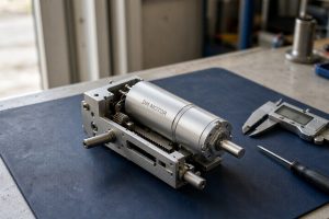
Electronic mortise lock body opened on a bench, with the gear motor driving the deadbolt through a pinion and sector gear.
What a Deadbolt Actually Asks the Motor to Do
A residential deadbolt is a small, dirty, high-friction linear actuator with a spring in the middle. Five requirements come out of that:
- Thrust, not torque. The bolt has to push 15–25 mm of steel through a strike plate that may be misaligned by 1–2 mm.
- Speed. Users judge a lock by sound and delay. Above about 1.5 s of motor run, the lock feels broken even when it is working.
- Holding. Once the bolt is home, the spring and any door preload push back. Something has to resist that without drawing current.
- Silence. A bedroom door at night is the acoustic reference; 45–55 dB(A) at 30 cm is the practical band.
- Energy per cycle. Ten to twenty actuations a day for a year is the realistic duty, and the cells are usually 4×AA.
Notice what is missing from that list: rated torque. It matters, but only after the thrust is known. The general method — load first, then speed, then thermal margin — is the same one we use across motor selection for a new mechanism.
From Bolt Thrust to Motor Torque
The bolt is normally driven by a pinion on the motor shaft engaging a rack or a sector gear cut into the bolt tail. For that arrangement the torque at the pinion is simply:
T = F × r
where F is the total resistance in newtons and r is the pinion pitch radius in metres. Split F into three parts, because they behave differently:
| Component | Typical value | How it varies |
|---|---|---|
| Sliding friction on the bolt | 15–40 N | Rises with dirt, drops with grease, rises sharply if the strike is misaligned |
| Return spring | 5–15 N | Fixed by design; acts against the motor in one direction only |
| Strike/frame interference | 0–20 N | Worst case is a sagging door; can double the friction term |
Take a greased steel bolt with 40 N of normal load, a friction coefficient of 0.15 (reference values for steel on steel), a 12 N spring and 10 N of interference:
- Friction force = 40 × 0.15 = 6 N
- Total F = 6 + 12 + 10 = 28 N
- With a pinion pitch radius of 4 mm: T = 28 × 0.004 = 0.112 N·m = 1.14 kgf·cm
That is the number the motor must deliver continuously through the whole stroke, not just at the end. On a 1:107 three-stage planetary box with a 73 % efficiency, a rated output of 7.9 kgf·cm gives roughly 7× margin over that load. On a 12 mm spur box at 1:250 with 1.12 kgf·cm rated, the margin is 1.0× — the lock works on a bench and fails on a cold door.
The same arithmetic applies to any small DC planetary gear motor driving a linear load: pinion radius is the lever, and it is the one design variable that costs nothing to change early.
Our rule for lock drives: size to 3× the measured running torque, not 3× the calculated one, because the calculated one always misses the strike plate.
Working the stroke time
Bolt travel is set by the lock body, usually 20 mm. With an 8 mm pinion (25.1 mm circumference) the motor has to turn 20 / 25.1 = 0.80 revolutions. At 58 rpm that is 0.83 s of motor run; at 37 rpm, 1.3 s. This is why ratio selection is a timing decision as much as a torque decision.
Three Datasheet Rows, Read Properly
The table below is the full published data for three variants of the same 22 mm platform plus one 12 mm unit. Read across a row, not down a column.
| Parameter | DM-22PM2247 12 V, 1:107 | DM-22PM2247 12 V, 1:152 | DM-22PM2247 24 V, 1:204 | DM-12SMN30 6 V, 1:250 |
|---|---|---|---|---|
| No-load speed | 63 rpm | 47 rpm | 44 rpm | 100 rpm |
| No-load current | 0.15 A | 0.17 A | 0.21 A | 0.19 A |
| Rated speed | 58 rpm | 37 rpm | 37 rpm | 86.9 rpm |
| Rated torque | 7.9 kgf·cm | 23.7 kgf·cm | 33.2 kgf·cm | 1.12 kgf·cm |
| Rated current | 0.77 A | 0.88 A | 1.26 A | 0.477 A |
| Stall torque | 48 kgf·cm | 121 kgf·cm | 121.1 kgf·cm | 5.7 kgf·cm |
| Stall current | 3.99 A | 3.88 A | 6.39 A | 1.893 A |
| Gearbox efficiency | 73 % | 65 % | 65 % | 59 % |
| Breaking torque | 4 N·m | 5 N·m | 5 N·m | 2 N·m |
Two things jump out. First, stall current is 5× rated current on the 22 mm units and 4× on the 12 mm unit. Second, going from 1:107 to 1:152 triples the rated torque but only adds 10 % efficiency loss — the torque comes from ratio, the heat comes from efficiency, and they do not scale together.
The breaking torque column matters more than most people realise. On the 22 mm platform, the gearbox is rated to survive 4–5 N·m before the gears shear, but the motor can only produce about 0.47 N·m at stall on the 1:107 version. On the 1:152 version, stall torque is 1.19 N·m — still under the gearbox limit. If you push to a 1:509 five-stage unit and ask for stall conditions, the gearbox becomes the fuse.
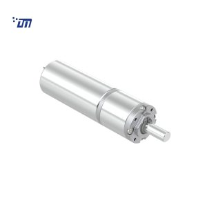
DM-22PM2247 with the 22 mm metal planetary gearbox and rear terminal tabs; the gearbox length grows from 15.2 mm at one stage to 33.6 mm at five.
The Battery Budget Nobody Runs
Four alkaline AA cells give about 2,000 mAh of nominal capacity, and roughly 800–1,200 mAh of usable capacity at the currents a lock actually pulls. Work the daily energy first:
- 10 actuations × 1.2 s × 0.77 A = 9.2 A·s = 2.6 mAh per day
- Sleep current 25 µA = 0.02 mAh per day
- Boost converter at 85 % efficiency: 2.6 / 0.85 = 3.1 mAh per day
Against 1,000 mAh usable that is roughly 320 days on paper, and 8–12 months in the field once cold weather, cell self-discharge and the standby draw of the radio are included. The motor is not usually the problem. The 2.4 GHz radio and the wake-on-approach sensor are.
The voltage sag test that predicts field failures
An alkaline AA has 0.15–0.25 Ω of internal resistance when fresh, more when cold. Four in series gives a 0.6–1.0 Ω string. At rated current that is a 0.5–0.8 V drop; at stall current on a 12 V pack it is 1.5 V or more.
Put the pack on a bench supply set to 4.5 V, run ten cycles back to back, and watch the current waveform on the first 100 ms. If the supply has to current-limit, the lock will behave differently on a cold morning than in the lab. The fix is not a bigger motor; it is a current-limited driver and a firmware timeout, typically 1.5 s, that stops the motor before the cells collapse.
Holding, Back-Driving and the Key Override
A planetary gearbox is back-drivable at moderate ratios. That is good for a key override — you can turn the output by hand and the motor spins along — and bad for holding, because a spring-loaded bolt will push the motor backwards as soon as power is removed.
Three ways to deal with it, in order of cost:
- Detent in the mechanism. A spring-loaded ball or a profiled cam holds the bolt; the motor only has to overcome it during the stroke. Cheapest, and the most common solution in residential locks.
- Motor braking. Short the windings after the stroke; the generated current creates a damping torque. Costs nothing, but it only holds while the short is applied, so the driver has to stay powered.
- Self-locking gearbox. A worm stage holds position without power. It also blocks the manual override unless a clutch is added, which is why lever-handle locks with worm drives are rare in residential products.
If you are specifying a lock for a market where a mechanical key must work during a power failure, do not let a self-locking gearbox into the design without a clutch. It is a compliance issue, not a preference.
The holding problem is not unique to locks. Access-control hardware with the same physics — turnstile and gate operators — solves it with a solenoid detent and a motor that only ever drives one direction. Copying that architecture into a deadbolt removes the holding question entirely and cuts the motor run time.
Noise Is a Gear Decision, Not a Motor Decision
The dominant noise source in a small gear motor at 60 rpm output is the first gear mesh, not the brushes. Practical numbers at 30 cm:
- 12 mm spur box, plastic first stage: 40–45 dB(A)
- 22 mm planetary, all metal: 48–55 dB(A)
- 22 mm planetary, POM first stage and metal planet carrier: 45–50 dB(A)
Two things move the number more than any other change: gear module (0.3 vs 0.4 changes contact ratio and whine) and the concentricity of the output bearing bore. A 0.05 mm bore offset can add 3–5 dB(A) at the same gear set — which is why the same drawing from two suppliers can sound completely different. Door operators built around the same gearboxes run into exactly this problem, and the fixes are the same ones described in our automatic door gear motor solutions.
Measure at thermal equilibrium, after 20 minutes of cycling. Grease thins, clearances open, and a unit that measured 46 dB(A) cold will read 50 dB(A) warm.
Cycle Life: The Duty You Did Not Write Down
Published lock life targets sit between 10,000 and 20,000 cycles. At 10 cycles a day that is three to five years, and the arithmetic is reassuring until you look at what actually fails:
- Brush wear on a 12 V unit at 1.2 s per cycle: 10 cycles/day = 12 s/day = about 1.2 hours of brush running per year. Brushes rated 300–1,000 hours are not the limit.
- Grease migration off the planet gears after 5,000–8,000 cycles is the usual mechanical end point.
- Stall events are the real killer. One jammed bolt held at stall for 5 s puts more heat into the gearbox than a week of normal cycles, and it can soften a POM first stage permanently.
So the motor datasheet’s life figure tells you very little. Ask for a cycle test report at your actual stroke, with the stall protection active, and look at the noise at cycle 1 versus cycle 10,000. A 5 dB(A) rise means the gear mesh is wearing.
Cold Weather, Door Sag and the Two-Times Rule
Three field conditions push a marginal design over the edge:
- Cold. At −10 °C, grease channelling torque rises 1.5–2× and alkaline capacity drops by about half. A lock that draws 0.77 A at 20 °C may draw 1.1 A at −10 °C for the same thrust.
- Door sag. A 2 mm drop at the strike turns into 20–40 N of extra normal load on the bolt face, which is the same order as the entire friction term.
- Worn strike plate. A burr raised by a year of use behaves like a 3 mm step and can double the peak thrust mid-stroke.
The two-times rule handles all three: design for 2× the worst measured thrust at 20 °C, and the cold case lands at roughly 1× with the current limit still doing its job.
For gate and outdoor lock hardware, the sealing spec matters as much as the grease: IEC 60529 is the standard behind the IP54, IP65 and IP67 ratings that most of these tenders quote, and it defines the test conditions — jet, spray or immersion — that a shaft seal has to survive.
Where Smart Lock Projects Actually Fail
Three opinions, formed from watching small lock drives come back:
Spend the length on diameter. A 22 mm planetary at 1:107 gives 7.9 kgf·cm at 58 rpm in a 43.9 mm gearbox. A 12 mm spur box at 1:250 gives 1.12 kgf·cm — a seventh of the torque, at a fifth of the diameter, and with a 59 % efficiency that turns most of the loss into heat inside a sealed housing. If the lock body has 45 mm of depth, use it. The trend toward 12 mm drives is driven by housing thickness, not by engineering.
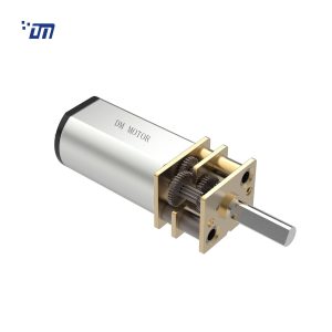
DM-12SMN30 at 1:250 fits a 12 mm housing but rates 1.12 kgf·cm at 0.477 A, which leaves no margin for a misaligned strike plate.
Stall protection is cheaper than torque. A 3.99 A stall on a 1.5 s timeout needs a driver rated 5 A and a PTC or firmware cut-out. That is a two-dollar problem. Upsizing the motor to avoid the stall costs tooling changes, volume and battery life.
Metal everywhere is not automatically better. An all-metal 22 mm box is the right choice for a commercial lock at 40 cycles a day. For a residential deadbolt at 10 cycles a day, a POM first stage is quieter and does not wear out within the product life. Match the material to the duty, not to a spec sheet rivalry.
The RFQ: Nine Numbers to Send a Supplier
Give a motor supplier these nine values and you will get a usable quotation instead of a catalogue page:
- Measured peak bolt thrust in newtons, on the real door, cold and warm
- Pinion or sector pitch radius in millimetres
- Bolt travel and maximum acceptable stroke time
- Supply voltage and cell chemistry, with the minimum voltage at end of life
- Maximum current the driver and cells can supply for 1 s
- Cycles per day and target life in cycles
- Ambient range, including storage temperature
- Noise limit in dB(A), with measurement distance and load condition
- Shaft or gear interface, connector type, and lead length
Item 4 is the one most often skipped, and it is the one that decides whether a 6 V or 12 V winding is correct.
What you should get back alongside the quotation is the inspection data for the batch: no-load current, rated current, stall current and noise. That is the same set of measurements we run on every unit — the process is described on our quality control page — and if a supplier cannot send it, ask for a sample and run the four numbers yourself.
FAQ
Can I run a 12 V gear motor from four AA cells?
Not directly. Four alkaline cells give 6.0 V fresh and about 4.4 V at end of life. A 12 V winding will run slowly and stall early at that voltage. Either use a 6 V winding, or use eight cells, or add a boost converter — and then budget 15–18 % of the energy as converter loss plus the extra quiescent current, which is often worse than the motor draw in standby.
Should I design to stall torque or rated torque?
Rated torque. Stall torque is 4–6× rated on these platforms and exists only to tell you what the current limit must survive. A design that needs stall torque to move the bolt will fail on the second cold morning, because the gear train is not rated for continuous operation at that point.
Why does my prototype work on the bench and jam on the door?
Because the bench has no strike plate. Door sag, paint build-up and a misaligned strike add 20–40 N of normal load, which is often more than the friction term the prototype was designed around. Measure the thrust with the lock installed and the door closed before you change the motor.
Do I need an encoder in a deadbolt?
Only if the mechanism has no mechanical end stop. For a bolt with hard stops, a current-based stall detect plus a fixed timeout is enough and costs no length. An encoder adds 3–6 mm to the gearbox and a wire pair, and it does not tell you the bolt is actually home — a limit switch does that better.
Is a metal gearbox always noisier?
Not always, but it is harder to make quiet. Metal planet gears transmit mesh frequency into the housing more efficiently than POM. The usual compromise in residential locks is a POM first stage with metal subsequent stages, which keeps the torque rating and removes most of the whine.