
Robotic Lawn Mower Motors: How to Choose the Right Motors for Your Machine
Robotic lawn mowers have quietly become one of the fastest-growing categories in outdoor power equipment. Behind the RTK antennas and vision cameras, though, the machine still rises or falls on three motor systems: the wheel drive motors that move it across the lawn, the cutting motor that spins the blade, and the height adjustment motor that sets cutting height. Get any of these wrong and the symptoms show up quickly in the field — weak climbing on slopes, short runtime, noisy cutting, and warranty claims that eat into margin.
This guide is written for the people who actually have to specify those motors: OEM engineers and procurement teams developing a robotic mower platform. It covers what to calculate first, where brushed and brushless architectures each make sense, how outdoor duty changes the specification, and the selection mistakes we see most often when manufacturers move from datasheet to prototype.
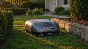
The Three Motor Systems Inside a Robotic Lawn Mower
A robotic mower is not one motor problem — it is three very different ones, and treating them the same way is usually where projects go wrong.
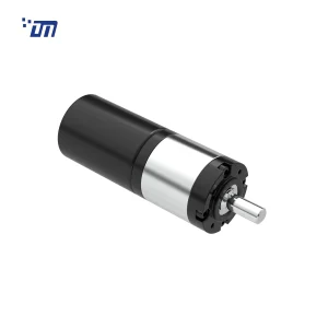
Wheel Drive Motors
Wheel drive is the most demanding of the three. The motor has to deliver enough torque to climb wet grass on a slope, hold position, and accelerate a machine that may weigh 8–15 kg with battery, while staying quiet enough not to disturb a garden at dusk. Because the wheels are the only contact with the ground, torque at the wheel — not motor RPM — is what determines real-world performance.
This is why most mid-range and premium platforms have converged on BLDC planetary gear motors for wheel drive: the planetary stage packs a high reduction ratio into a short axial length and keeps the output shaft concentric with the motor, which makes packaging into a narrow wheel hub far easier.
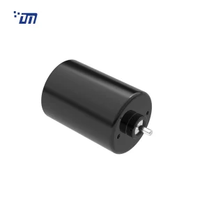
The Cutting Blade Motor
The cutting motor is a different animal. Small domestic mowers typically run one or three small blades at high speed; larger commercial platforms run disc-style cutting systems. The cutting motor is usually a bare brushless DC motor rather than a geared unit — the blade is mounted directly on the shaft, and the operating point sits at high speed with a load profile that spikes every time the blade hits denser grass.
Because the load is irregular, the controlling variable is not the rated torque on the datasheet but how the motor’s torque-speed curve behaves under that spike — and how quickly the controller can recover speed without drawing a current spike that collapses battery voltage.
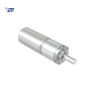
Blade Height Adjustment Motor
Cutting height adjustment is a low-speed, high-precision positioning task. The motor needs to move a deck or blade carrier against gravity and friction, hold position without drifting, and often works through a worm or high-ratio planetary stage where self-locking matters. Compact DC planetary gear motors in the 16–28 mm range are typical here, and on many platforms this is the single smallest actuator in the whole machine — which is exactly why it is the easiest one to under-specify.
Start From the Machine, Not From the Motor
The most common failure in motor selection is starting from a motor and trying to make the machine fit. The better sequence is to define the machine’s worst-case operating condition and work backwards.
If motor selection is new to your team, our general guide to choosing the right motor covers voltage, torque and gear ratio from first principles. The rest of this page assumes that framework and adds what a mower makes harder: slope, wet grass, sealing and blade duty.
How to Calculate Wheel Drive Torque
For a wheeled machine on a slope, the tractive force needed is:
F = m · g · (sin θ + f · cos θ) / n_drive
where m is total machine mass, θ is the slope angle, f is the rolling resistance coefficient and n_drive is the number of driven wheels. Torque at each wheel is then:
T_wheel = F · r_wheel
And to convert that into a motor requirement:
T_motor = T_wheel / (i · η_gearbox) and n_motor = n_wheel · i
Worked example — a 12 kg machine (with battery) climbing a 30% slope on grass:
| Parameter | Value |
|---|---|
| Machine mass m | 12 kg (with battery) |
| Slope | 30% (θ ≈ 16.7°) |
| Rolling resistance f (grass) | 0.15 |
| Wheel radius r | 90 mm |
| Driven wheels | 2 |
| Total tractive force F | ≈ 50.7 N |
| Force per driven wheel | ≈ 25.4 N |
| Torque at wheel | ≈ 2.28 N·m ≈ 23 kgf·cm |
| With 30% design margin | ≈ 3.0 N·m ≈ 30 kgf·cm |
| Target mowing speed | 0.4 m/s → ≈ 42 rpm at the wheel |
| Motor speed | ≈ 5000 rpm → gear ratio i ≈ 120:1 |
| Gearbox efficiency (multi-stage planetary) | ≈ 0.65 |
| Required motor torque | ≈ 38 mN·m at ~5000 rpm |
Two things in that last row matter more than they look. First, the requirement is not “a 3 N·m motor” — it is a motor that can deliver roughly 38 mN·m continuously at around 5000 rpm through a 120:1 gearbox. Second, 30% slope on dry grass is not the worst case: wet grass can push the rolling resistance coefficient well above 0.15, and wet grass plus a 40% slope is the condition that actually breaks under-specified drives.
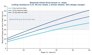
The chart below shows how quickly that requirement grows with slope, which is why a drive motor that works fine on a flat test lawn will stall on the first real hill.
Continuous Torque, Peak Torque and Why Stall Torque Misleads
Datasheets usually list four torque figures: rated, maximum continuous, peak and stall. Of these, stall torque is the one most often misused in selection — it is the torque at zero speed with a very high current draw, and no thermal design can sustain it.
For a robotic mower, size the drive motor against continuous torque at the operating speed for normal mowing, and check that peak torque plus the gearbox’s allowable output torque covers start-up on the steepest slope in the specification. Note that the gearbox, not the motor, is often the limiting component: a motor that can deliver high instantaneous torque can still strip a small gear train if the output load exceeds the gearbox rating.
Brushed or Brushless?
| Brushed DC gear motor | Brushless (BLDC) gear motor | |
|---|---|---|
| Relative cost | Lower | Higher (motor + driver) |
| Efficiency | Moderate; more of the battery budget spent on heat | Higher, especially at partial load — directly buys runtime |
| Life | Limited by brush wear | Effectively limited by bearings and gearbox |
| Noise and EMI | More brush noise, more electrical noise | Quieter, cleaner EMC when properly driven |
| Control | Simple 2-wire drive | Needs a driver (or built-in driver / FOC) |
| Typical fit | Entry-level machines, cost-driven auxiliary mechanisms | Mid and premium platforms, commercial duty |
The trade-off is really about duty cycle. A mower that runs a few hours a week on a small lawn can be engineered around brushed motors. A machine that runs daily, several hours a day, on a large property — or any commercial platform — will find brush wear becomes the dominant failure mode, and the higher upfront cost of a brushless drive pays back in runtime and warranty. We have covered the underlying differences in more detail in brushed vs. brushless DC motors.
IP Rating: Outdoor Duty Changes the Specification
A motor that performs correctly on a bench test can still fail in the field if ingress protection was an afterthought. Ingress protection is defined by the IEC in standard 60529, where the first digit covers solids and the second covers water; the terminology used across motor datasheets can be cross-checked in the IEC Electropedia.
For robotic mowers, what matters in practice:
- Wheel drive motors see rain, dew, irrigation water and grass debris. IP54 is a common minimum; platforms that park outdoors in wet climates often specify IP65 or better on the drive assembly.
- Cutting motors are exposed to grass clippings, moisture and impact debris — sealing and bearing design here decides whether clippings migrate into the windings.
- Height adjustment motors are usually better protected by their position in the chassis, but still need sealing against dust and moisture over a long service life.
The important point is that IP is a system property, not a motor property — sealing at the shaft, the cable entry and the housing interface all have to be engineered together, and re-rating a motor from indoor to outdoor duty late in a project usually means re-engineering the housing entirely. We wrote about this in more detail for another outdoor application in waterproof DC motors for solar tracking systems.
Encoders and Hall Sensors: When They Earn Their Cost
A feedback device adds cost and complexity, so it is worth being specific about when it pays for itself on a mower:
- Wheel odometry for navigation. RTK- and vision-based platforms still need wheel odometry as a cross-check between position fixes, especially under tree canopies where satellite reception drops.
- Differential steering. Independent left/right wheel speed control needs feedback to turn predictably on uneven ground.
- Closed-loop speed control. Keeping cutting speed constant as load changes requires knowing actual speed, not commanded speed.
- Slope hold and low-speed stability. Open-loop drives tend to hunt at very low speeds on a slope.
For most platforms this means hall sensors on the wheel drive motors; where hall sensors versus encoders is the question, halls win on cost and robustness for speed feedback, and incremental encoders are justified mainly where position accuracy in the height adjustment axis is a selling point.
Five Selection Mistakes We See Most Often
- Sizing by no-load speed. A 5000 rpm no-load rating says nothing about what the motor does at 42 rpm through a gearbox under load. Always work from the torque-speed curve at the operating point.
- Ignoring the gearbox torque limit. The motor survives; the gears do not. The allowable continuous and peak output torque of the gearbox is a separate specification and must be checked independently.
- Sizing to dry-grass conditions. Wet grass roughly doubles rolling resistance. If the requirement is written from a dry summer test lawn, the first autumn will find the gap.
- Leaving IP and sealing to the last revision. Outdoor sealing affects housing design, bearing selection, cable routing and venting — retrofitting it late in development is far more expensive than specifying it up front.
- Forgetting the cutting motor’s duty cycle. A blade motor that handles a five-minute bench run happily can overheat on a sixty-minute continuous mow at rated load. Thermal validation has to happen on the finished machine, with real grass.
What to Ask a Motor Supplier Before You Sample
Before committing to samples, these are the questions that separate a motor supplier from a drive partner:
- Can you provide the full torque-speed and efficiency curves, not just a spec table?
- What is the gearbox’s allowable continuous and peak output torque, and its tested efficiency at my ratio?
- Can you supply IP test reports for the protection level being quoted, not just a claim on the datasheet?
- What life test data exists for the specific gear train and bearing set being proposed?
- How is the driver integrated — external, built-in, or FOC with the customer’s firmware?
- What customisation is realistic: winding, ratio, shaft, connector, cable length, sensor configuration?
- What does the quality control process look like between sample approval and mass production?
That last question is often the one with the longest shadow. You can read about our quality control process and how it runs from incoming material to finished assembly.
Frequently Asked Questions
What motors are used in a robotic lawn mower?
Most robotic mowers use three separate motor systems: brushless planetary gear motors for wheel drive, a bare high-speed brushless motor for the cutting blade, and a compact geared DC motor for cutting height adjustment. Entry-level machines may still use brushed motors on auxiliary functions.
How much torque does a robot mower wheel motor need?
For a 10–12 kg machine with 90 mm wheels, expect roughly 20–40 kgf·cm of torque per drive wheel after a design margin, depending on the target slope. The motor-side torque is that figure divided by the gear ratio and gearbox efficiency — typically a few tens of mN·m.
What IP rating should a lawn mower motor have?
Wheel drive motors are commonly specified at IP54 minimum, with IP65 or higher preferred for machines parked outdoors in wet climates. Ingress protection is defined in IEC 60529 and must be engineered at the shaft seal, cable entry and housing interface together.
Is brushless worth it for a robotic mower?
For machines that run daily or for long seasons, yes. Higher efficiency buys runtime from the same battery, brush wear disappears as a failure mode, and noise drops. For entry-level products with short duty cycles, a well-engineered brushed drive can still be the right cost decision.
Conclusion
Specifying robotic lawn mower motors is not a component-picking exercise — it is a system exercise that starts from the machine’s worst real-world condition. Work the torque calculation backwards from the slope and grass condition your customers actually mow in, size against continuous torque at the operating speed rather than stall torque, decide brushed versus brushless on duty cycle rather than on price alone, and treat IP rating and feedback as requirements from day one rather than revisions.
If you are developing a mower platform and want a second pair of eyes on the drive specification, our engineering team can review your load case and propose gear motor options — contact us to discuss torque, ratio, protection level and feedback configuration for your machine.
{acf_post_brief}