
DC Gear Motor Solutions for Automatic Pet Feeders
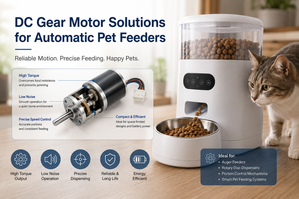
Why Automatic Pet Feeders Need a Gear Motor
An automatic pet feeder must dispense a relatively small amount of food at a controlled time while preventing the dispensing mechanism from jamming.
The motor therefore needs more than simple rotation. It must provide:
Sufficient output torque to overcome food resistance
Low and stable rotational speed
Repeatable rotation angle or revolutions
Low acoustic noise
Compact dimensions
Reliable operation over thousands of feeding cycles
For these reasons, a DC gear motor for automatic pet feeders is commonly used to drive augers, rotary dispensing wheels, gates, or portion-control mechanisms.
The gearbox converts the high-speed, low-torque output of a small DC motor into low-speed, higher-torque mechanical motion.
[T_{out}=T_m \times i \times \eta]
[n_{out}=\frac{n_m}{i}]
where (T_m) is motor torque, (i) is gear ratio, and (\eta) is gearbox efficiency.
Torque Is Critical When Food Causes a Jam
The required torque of a pet feeder is not constant.
Dry kibble can accumulate around an auger or dispensing wheel and temporarily increase mechanical resistance. Irregular food pieces can also create transient peak loads.
A practical design model is:
[T_{req}=T_f+T_{food}+T_{acc}]
where:
(T_f) = bearing and mechanical friction
(T_{food}) = resistance generated by food
(T_{acc}) = torque required for acceleration
For a vertical or inclined auger, gravity and material pressure may further increase the load.
The selected high torque DC gear motor for pet dispensers should therefore be evaluated using both continuous torque and peak torque, rather than relying only on rated torque.
A reasonable engineering design should also include a safety factor based on actual food type, hopper geometry, and the probability of blockage.
Gear Ratio Controls Dispensing Speed
Pet feeders normally require relatively slow output rotation. A small DC motor may operate at several thousand RPM, while the dispensing mechanism may need only tens of RPM or less.
For example:
Motor speed = 3,000 rpm
Gear ratio = 60:1
Ignoring losses:
[n_{out}=\frac{3000}{60}=50\ rpm]
The gearbox simultaneously increases available output torque.
However, an excessively high reduction ratio can introduce additional friction, increase gearbox size, and reduce overall efficiency.
Therefore, DC gear motor torque and speed selection should start from the required dispensing cycle.
For example:
Required dispensing rotation → required output RPM → required output torque → gear ratio → motor specification
This is more reliable than selecting a motor based only on physical size.
Speed Stability Directly Affects Portion Accuracy
For an auger-based feeder, the amount of food delivered is related to screw geometry, rotational speed, and operating time.
A simplified relationship can be expressed as:
[M \approx K \times n \times t]
where:
(M) = dispensed food mass
(n) = auger rotational speed
(t) = operating time
(K) = experimentally determined feed coefficient
In practice, (K) varies with:
Kibble size
Food density
Moisture content
Auger pitch
Hopper geometry
Food bridging
Therefore, improving motor speed consistency can improve portion repeatability, but motor speed alone cannot guarantee a fixed gram quantity.
For production products, engineers should calibrate the actual feeder mechanism with the target food.
Why Low-Noise DC Gear Motors Matter
A pet feeder is often installed in a home environment, sometimes operating early in the morning or during the night.
Gearbox noise can come from:
Gear meshing
Motor brushes and commutation
Bearing vibration
Gear eccentricity
Shaft imbalance
Structural resonance
A low noise gear motor for automatic pet feeders should therefore be evaluated as a complete mechanical system.
Useful design measures include:
Optimized gear tooth profiles
Proper gear center-distance control
High-quality bearings
Appropriate lubrication
Balanced rotor design
Reduced gearbox clearance
Isolation between motor and plastic housing
Simply specifying a low dB motor is not enough. The final feeder enclosure can amplify gearbox vibration and become the dominant noise source.
Brushed vs BLDC Gear Motors
Brushed DC Gear Motor
A brushed DC motor with gearbox for pet feeder is attractive for cost-sensitive products because it requires relatively simple electronics.
Advantages include:
Low controller cost
Simple PWM speed control
High starting torque
Easy forward/reverse control
Compact motor options
The main limitation is brush and commutator wear, particularly when the feeder operates frequently over a long service life.
BLDC Gear Motor
A BLDC gear motor eliminates mechanical brushes and can provide longer operating life and improved efficiency.
It is attractive for premium automatic feeders requiring:
Long service life
Lower maintenance
Higher efficiency
Frequent operating cycles
Closed-loop speed control
However, BLDC systems require electronic commutation and generally have a higher system cost.
Motor Position Feedback Improves Jam Detection
For a basic feeder, the motor can operate using a simple timed command.
A more advanced design can monitor motor current or encoder feedback.
For example:
Normal operation:
Motor current → stable range
Food blockage:
Motor torque increases → current increases → controller detects abnormal load → motor stops or reverses
This approach can protect both the gearbox and dispensing mechanism.
A DC gear motor with encoder can provide additional information about:
Motor speed
Rotation count
Dispensing cycles
Stall conditions
Position
For higher-end automatic feeders, encoder feedback can therefore improve system diagnostics and feeding reliability.
Gearbox Selection for Automatic Pet Feeders
Different gearbox architectures provide different performance characteristics.
| Gearbox Type | Advantages | Typical Consideration |
| Spur Gearbox | Low cost, compact, simple | Noise and wear at higher speed |
| Planetary Gearbox | High torque density, compact | Higher cost |
| Worm Gearbox | High reduction, strong holding effect | Lower efficiency |
| Custom Gear Train | Optimized for specific mechanism | Higher development cost |
For compact feeders, a micro DC gear motor for pet feeder applications often uses a spur or planetary reduction stage.
If the dispensing mechanism needs a very high reduction ratio and resistance to reverse movement, a worm gearbox may also be considered, although its efficiency must be evaluated.
Electrical Design: Voltage, Current and Stall Protection
A typical low-voltage pet feeder may use a DC motor powered from a battery or AC/DC adapter.
Important parameters include:
Rated voltage
No-load speed
Rated speed
Rated torque
Stall torque
No-load current
Rated current
Stall current
The controller and power supply must be capable of handling the motor’s transient current.
Stall current can be several times higher than normal operating current. If the auger becomes blocked and the controller continues powering the motor, excessive current can cause:
Motor overheating
Driver failure
Gear tooth damage
Power supply protection
Premature brush wear
Therefore, stall detection and current limiting should be part of the overall feeder design.
How to Select a DC Gear Motor for a Pet Feeder
Engineers can use the following selection process:
Step 1: Define the dispensing mechanism
Determine whether the motor drives an auger, rotary wheel, flap, gate, or conveyor.
Step 2: Measure actual load torque
Measure starting torque and running torque using the real food and hopper.
Step 3: Determine output speed
Calculate the required RPM from dispensing time and mechanism geometry.
Step 4: Select the gear ratio
[i=\frac{n_m}{n_{out}}]
Then verify the actual output torque after gearbox efficiency.
Step 5: Check peak load
Simulate or test jam conditions rather than using only normal feeding loads.
Step 6: Evaluate noise
Test the complete motor + gearbox + feeder housing assembly.
Step 7: Select feedback
Choose open-loop control, current sensing, Hall feedback, or an encoder according to the required feeding accuracy and jam protection.
Step 8: Verify service life
Consider the expected number of feeding cycles over the product’s lifetime.
Custom DC Gear Motors for Automatic Feeders
For mass-produced pet feeders, an off-the-shelf motor may not provide the optimum combination of torque, speed, noise, dimensions, and mounting requirements.
A custom DC gear motor for automatic feeder applications can be optimized for:
Output shaft diameter
Shaft length
Mounting holes
Gear ratio
Rated voltage
Output RPM
Torque
Encoder configuration
Connector type
Noise level
Gearbox material
Lubrication
Duty cycle
For example, if the feeder has limited internal space, a custom gearbox can be designed around the available mechanical envelope rather than forcing the product around a standard motor.
Key Engineering Considerations
The motor should be selected as part of the complete dispensing system.
The most important parameters are:
Output Torque → Output Speed → Gear Ratio → Noise → Stall Protection → Duty Cycle → Service Life
A reliable DC gear motor for automatic pet feeders should provide enough peak torque to overcome food blockage without being unnecessarily oversized.
For engineers developing automatic pet feeders, the best motor is not necessarily the motor with the highest torque. It is the motor that provides the required torque and speed with predictable operation, acceptable noise, sufficient thermal margin, and reliable performance throughout the product’s service life.
FAQ
What type of motor is best for an automatic pet feeder?
A small DC gear motor is a practical choice for many automatic feeders because it provides low-speed, high-torque output in a compact package. Planetary or spur gearboxes can be selected according to torque, noise, cost, and space requirements.
How much torque does an automatic pet feeder motor need?
There is no universal torque value. Required torque depends on auger geometry, food type, hopper design, friction, and blockage conditions. Engineers should measure actual running and peak torque using the final dispensing mechanism.
Why does an automatic pet feeder need a gearbox?
A gearbox reduces the high rotational speed of the DC motor while increasing output torque. This allows a small motor to drive a slow-moving auger or dispensing wheel.
Can a DC gear motor detect a food blockage?
Yes. A controller can detect a blockage by monitoring motor current, speed, or encoder feedback. A sudden increase in current or reduction in speed can trigger a stop-and-reverse protection strategy.
Is a BLDC gear motor better than a brushed DC gear motor for pet feeders?
For high-cycle, long-life products, BLDC gear motors can offer advantages in efficiency and mechanical life. For cost-sensitive feeders with relatively low operating frequency, brushed DC gear motors can provide a simpler and more economical solution.