
DC Motor Overheating Causes & Prevention: Thermal Management in Enclosed Applications
Why Do DC Motors Overheat?
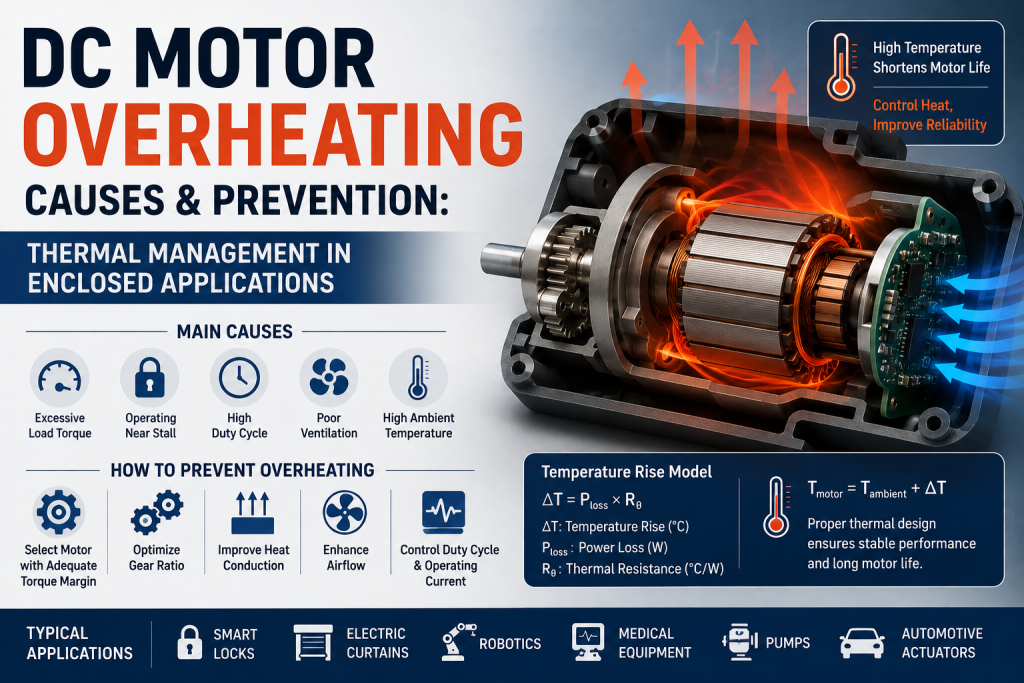
DC motor overheating occurs when the heat generated inside the motor exceeds the heat that can be dissipated to the surrounding environment.
For compact motors, especially DC gear motors installed inside enclosed equipment, thermal management can become a critical design issue. A motor may operate correctly during short functional tests but reach excessive temperatures during continuous or repeated operation.
The main sources of heat are:
Copper loss in the windings
Iron/core loss
Brush and commutator losses
Bearing and mechanical friction
Gearbox losses
Excessive load or stall conditions
For most small brushed DC motors, I²R copper loss is one of the most important contributors to winding temperature rise.
Main Causes of DC Motor Overheating
Excessive Load Torque
When a motor operates under a load close to its maximum capability, winding current increases.
Copper loss approximately follows:
PCu = I²R
This means that a relatively small increase in current can produce a much larger increase in winding heat.
For example, increasing motor current from 1 A to 1.5 A increases the theoretical copper loss by:
(1.5 / 1)² = 2.25
Therefore, continuously operating a motor near its maximum torque can create significant thermal stress.
Operating Near Stall
A DC motor stall condition is one of the most severe thermal conditions.
At stall:
Motor speed ≈ 0 RPM
Back EMF ≈ 0 V
Current approaches stall current
Heat generation increases rapidly
Because a motor produces little or no rotational airflow at zero speed, heat dissipation can also become less effective.
A motor designed for intermittent operation may tolerate a short stall event but fail if the stall condition continues.
Engineering recommendation: Never select a motor based only on stall torque. Use the required continuous operating torque and duty cycle as primary selection criteria.
High Duty Cycle
A motor rated for intermittent operation may overheat when used continuously.
For example, a motor operating at:
10 seconds ON
20 seconds OFF
has a significantly different thermal load from a motor operating continuously at the same torque.
The important parameters are:
Load + Speed + Operating Time + Rest Time + Ambient Temperature
Therefore, motor selection should consider the complete duty cycle, rather than only the peak torque requirement.
Why Enclosed Applications Are More Difficult
Enclosures significantly restrict heat transfer.
A motor can dissipate heat through:
Conduction through the motor housing and mounting structure
Convection to surrounding air
Radiation from the motor surface
In a sealed enclosure, natural convection is limited because hot air cannot easily exchange with cooler outside air.
This becomes particularly important for:
Smart locks
Electric curtains
Medical devices
Vending machines
Small pumps
Robotics
Automotive actuators
Compact automation equipment
A motor that runs safely in an open laboratory environment may experience a much higher temperature rise after installation inside a small plastic housing.
DC Motor Temperature Rise Calculation
A basic thermal model can be represented as:
ΔT = Ploss × Rθ
Where:
ΔT = motor temperature rise
Ploss = total motor power loss
Rθ = thermal resistance between the motor and ambient environment
The approximate motor temperature is:
Tmotor = Tambient + ΔT
For example, if a motor generates 8 W of heat and the effective thermal resistance is 8 °C/W:
ΔT = 8 × 8 = 64°C
At an ambient temperature of 25°C:
Tmotor ≈ 89°C
This simple calculation shows why thermal resistance and enclosure design are just as important as motor electrical specifications.
In real products, thermal resistance depends on motor size, mounting method, housing material, airflow, gearbox configuration, and enclosure geometry.
How to Prevent DC Motor Overheating
1 Select the Motor With Adequate Torque Margin
Avoid designing a system where the motor continuously operates at its maximum rated torque.
A reasonable torque margin helps reduce current and therefore reduces copper losses.
For a DC gear motor, engineers should evaluate:
Required load torque → Rated torque → Peak torque → Duty cycle
rather than selecting the motor based only on maximum or stall torque.
2 Optimize the Gear Ratio
An appropriate gearbox ratio can reduce the motor’s required operating torque.
For example, increasing the gear ratio can allow the motor to operate at a more favorable point on its torque-speed curve.
However, higher gear ratios also introduce additional gearbox losses and may reduce output speed.
Therefore, the optimal gear ratio should balance:
Output torque
Output speed
Motor current
Gearbox efficiency
Thermal load
3 Improve Heat Conduction
For an enclosed DC motor, mechanical mounting can become part of the thermal system.
Heat can be transferred from the motor housing into:
Metal brackets
Aluminum frames
Heat spreaders
Gearbox housings
Equipment chassis
A mechanically rigid metal mounting structure can therefore provide both mechanical support and thermal conduction.
4 Improve Airflow Where Possible
If the product allows ventilation, increasing airflow around the motor can reduce thermal resistance.
Possible solutions include:
Ventilation openings
Internal airflow channels
Cooling fans
Larger motor housing surface area
Thermally conductive mounting structures
For sealed products, forced airflow may not be possible, so conduction becomes especially important.
Brushed DC Motor vs. BLDC Motor: Thermal Considerations
A BLDC motor can provide thermal advantages in some applications because it eliminates mechanical brush and commutator losses.
BLDC motors are particularly attractive for:
Continuous-duty applications
High-speed operation
Long operating life
Compact high-power systems
Applications requiring high efficiency
However, BLDC thermal performance still depends on winding resistance, operating current, switching losses, motor efficiency, and cooling conditions.
Therefore, simply replacing a brushed motor with a BLDC motor does not automatically solve an overheating problem.
Practical Thermal Management Checklist
Before finalizing a motor for an enclosed application, engineers should verify:
| Parameter | Design Consideration |
| Ambient temperature | Maximum expected operating temperature |
| Continuous torque | Required load torque during normal operation |
| Peak torque | Short-duration acceleration or overload |
| Duty cycle | ON/OFF operating pattern |
| Motor current | Continuous and peak current |
| Temperature rise | Winding and housing temperature |
| Thermal resistance | Motor-to-ambient heat transfer |
| Gearbox efficiency | Additional heat generation |
| Enclosure | Sealed, ventilated, or open |
| Mounting | Plastic, aluminum, or metal structure |
A prototype thermal test under the worst-case load and ambient temperature is strongly recommended before mass production.
Common Applications Requiring Thermal Analysis
Thermal management is particularly important when a DC motor or DC gear motor is installed inside a compact enclosure.
Smart Locks
High torque during locking combined with limited ventilation can create localized heat around the motor and gearbox.
Electric Curtains and Blinds
Repeated opening and closing cycles require careful evaluation of duty cycle and motor temperature rise.
Medical Equipment
Low noise, reliability, and controlled temperature are often critical design requirements.
Robotics
Compact actuators can experience high torque density and limited heat dissipation.
Automotive Actuators
High ambient temperatures combined with enclosed installation conditions can significantly reduce available thermal margin.
Key Takeaway for Engineers
DC motor overheating is usually a system-level problem, not simply a motor problem.
The correct solution requires evaluating:
Motor → Load → Gear Ratio → Current → Duty Cycle → Mounting → Enclosure → Ambient Temperature
For enclosed applications, engineers should not rely solely on the motor’s rated torque or nominal temperature specification. The motor should be tested under the actual worst-case load, duty cycle, ambient temperature, and enclosure conditions.
A properly selected motor with sufficient torque margin, optimized gear ratio, effective heat conduction, and appropriate duty-cycle control can significantly improve reliability and operating life.
FAQ
What causes a DC motor to overheat?
The most common DC motor overheating causes include excessive load, high current, prolonged stall, insufficient cooling, high ambient temperature, excessive duty cycle, and gearbox losses.
How can I prevent a DC motor from overheating?
Select a motor with adequate torque margin, optimize the gear ratio, limit stall time, manage the duty cycle, improve heat conduction, and validate the design under worst-case thermal conditions.
Does a DC gear motor generate more heat than a DC motor?
A gear motor introduces additional mechanical losses through the gearbox. However, the correct gear ratio can also reduce the torque required from the motor and improve overall system efficiency.
What is an acceptable DC motor temperature rise?
There is no single value suitable for every motor. The allowable temperature depends on winding insulation class, materials, ambient temperature, operating duty, and manufacturer specifications. Always verify the manufacturer’s maximum winding and housing temperature limits.
Is overheating a problem for enclosed DC motors?
Yes. DC motor overheating in enclosed applications can be more severe because restricted airflow increases thermal resistance. Enclosure design and motor mounting should therefore be considered during the initial mechanical design stage.
Conclusion
Effective DC motor thermal management requires more than simply adding cooling. The most reliable approach is to reduce unnecessary heat generation while improving the motor’s ability to transfer heat to the environment.
For compact DC gear motors and BLDC motors, engineers should optimize motor selection, load torque, gear ratio, duty cycle, current, mounting structure, and enclosure design together.
This system-level approach provides better temperature control, longer motor life, and more reliable performance in demanding enclosed applications.